Bicycle disc brake rotor

a technology of disc brake rotor and rotor, which is applied in the direction of cycle brakes, cycle elements, cycle equipment, etc., can solve the problems that the braking action tends to generate a substantial amount of heat in the disc brake rotor, and achieves the effects of efficient heat radiating, excellent performance and easy production

Active Publication Date: 2013-07-04
SHIMANO INC
View PDF11 Cites 58 Cited by
  • Summary
  • Abstract
  • Description
  • Claims
  • Application Information

AI Technical Summary

Benefits of technology

[0005]While disc brake systems provide excellent performance, the braking action tends to generate a substantial amount of heat in the disc brake rotor. Thus, one aspect present in this disclosure is to provide a disc brake rotor with a configuration that more efficiently radiates heat from the outer portion of the disc brake rotor. Another aspect present in this disclosure is to provide a disc brake rotor with a cooling fin that relatively easy to produce.

Problems solved by technology

While disc brake systems provide excellent performance, the braking action tends to generate a substantial amount of heat in the disc brake rotor.

Method used


Image

  • Bicycle disc brake rotor
  • Bicycle disc brake rotor
  • Bicycle disc brake rotor

Examples


first embodiment

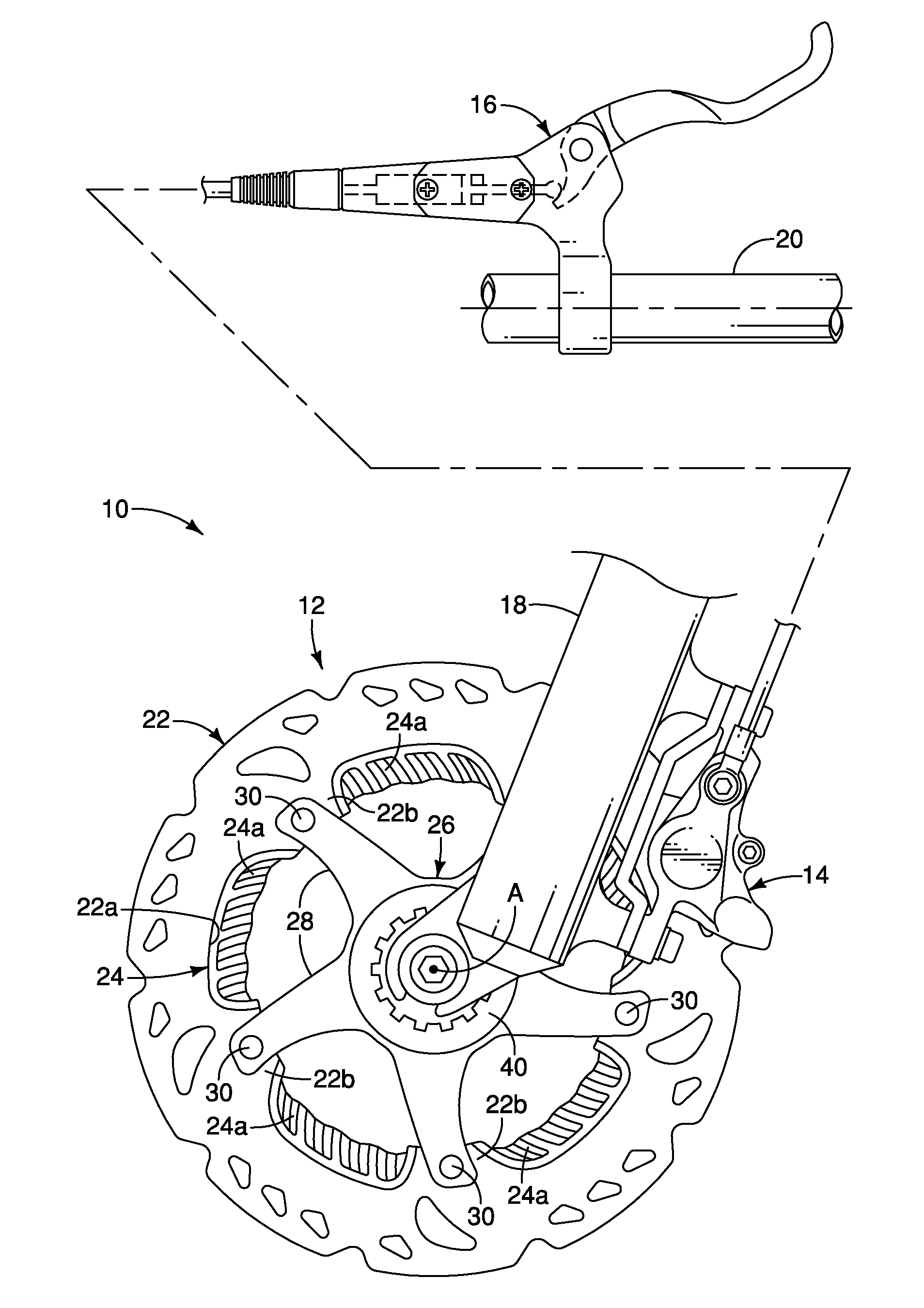
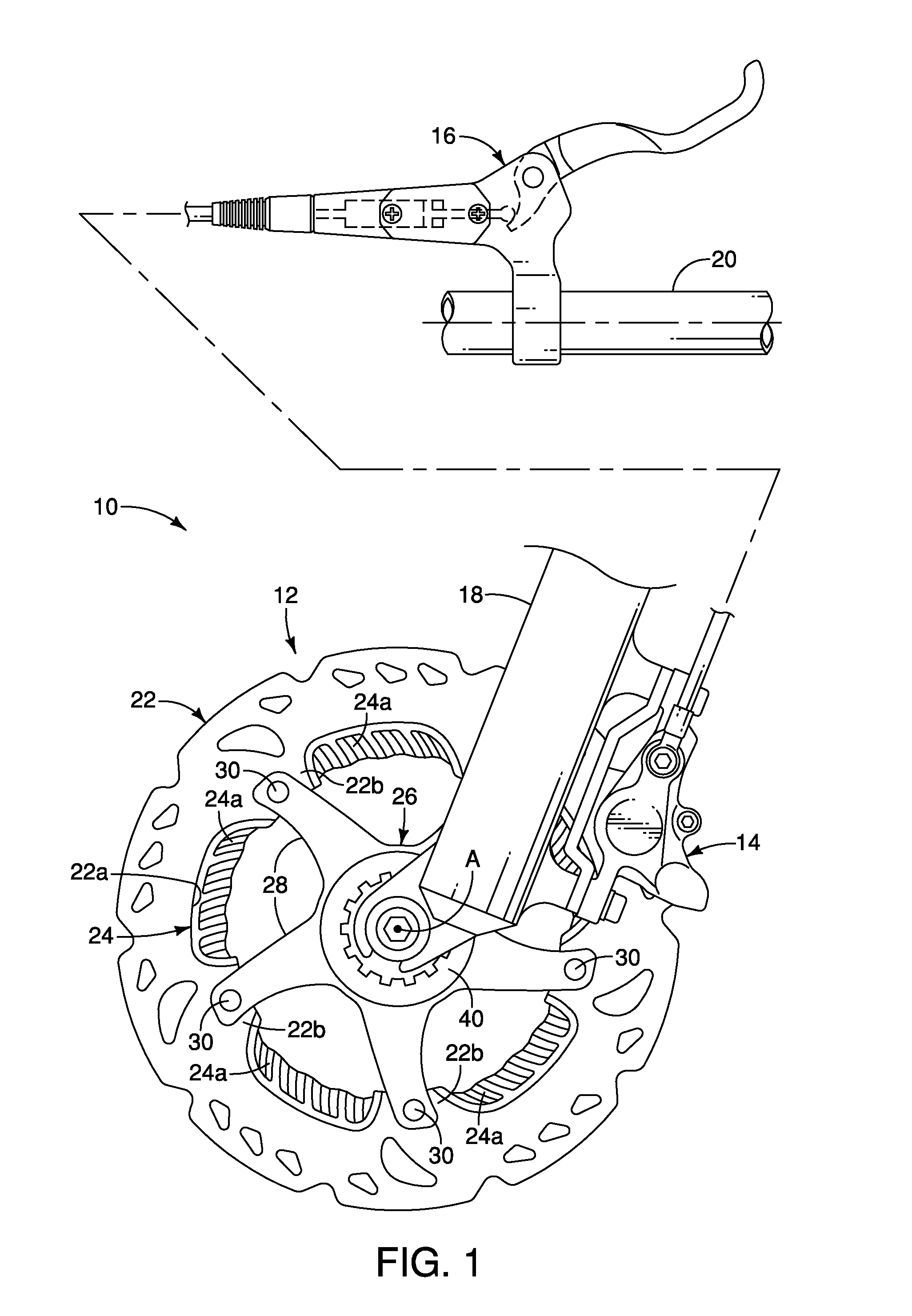
[0029]Referring initially to FIG. 1, a front disc brake system 10 is illustrated that includes a bicycle disc brake rotor 12 in accordance with a As explained below, the bicycle disc brake rotor 12 has a configuration that promotes cooling of the bicycle disc brake rotor 12. The front disc brake system 10 further includes a bicycle disc brake caliper 14 and a brake operating (actuating) mechanism 16. Basically, the bicycle disc brake rotor 12 is fixedly attached to a hub of a bicycle wheel (not shown). The bicycle disc brake caliper 14 is mounted to a bicycle fork 18, while brake operating mechanism 16 is attached to a bicycle handlebar 20. Since the operation and construction of the front disc brake system 10 is conventional, except for the construction of the bicycle disc brake rotor 12, the front disc brake system 10 will not be discussed or shown in further detail herein. Moreover, while the front disc brake system 10 is illustrated as a hydraulic braking system, the bicycle di...

third embodiment

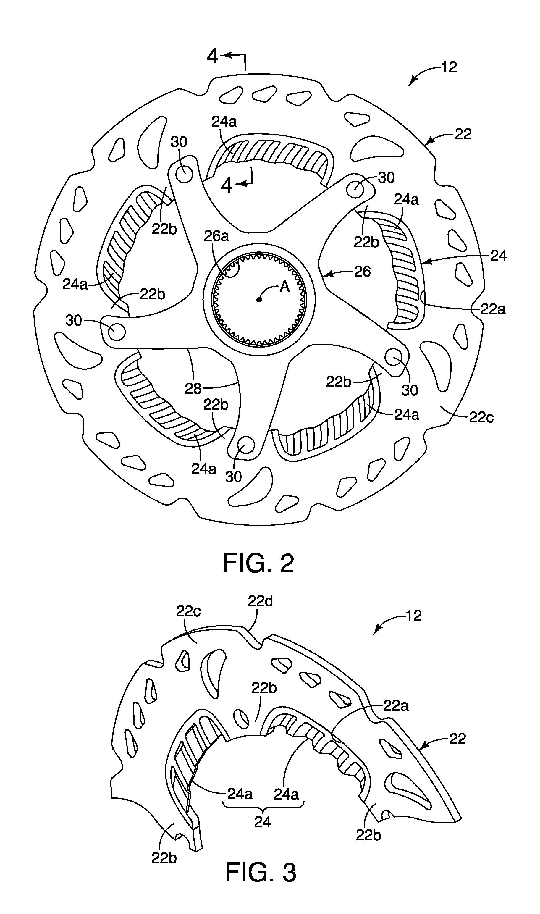
[0039]Here in the third embodiment, the fin portions 224a individually extending members that extend radially inward from the inner peripheral edge 222a of the outer portion 222 toward the center rotational axis A of the bicycle disc brake rotor 212. As seen in FIG. 9, the fin portions 224a are protrusions extending radially inward towards the center rotational axis A of the bicycle disc brake rotor 212. The cooling fin 224 has a plurality slits 225 separating the fin portions 224a in the circumferential direction of the outer portion 222. The fin portions 224a (e.g., the protrusions) are illustrated as elongated plates that are cantilevered relative to the outer portion 222. The fin portions 224a has flat axially facing surfaces with flat circumferentially facing surfaces such that the fin portions 224a have a rectangular cross sectional profile in the circumferential direction. However, the fin portions 224a can have other configurations such as circular, oval, teardrop, etc. as n...


PUM


Abstract

A bicycle disc brake rotor basically has an outer portion and a cooling fin. The outer portion has first and second base surfaces facing in opposite axial directions. The cooling fin is disposed radially offset from at least one of the first and second braking surfaces.

Description

BACKGROUND[0001]1. Field of the Invention[0002]This invention generally relates to a bicycle disc brake rotor. More specifically, the present invention relates to a bicycle disc brake rotor with a configuration that promotes cooling of the braking surfaces.[0003]2. Background Information[0004]In recent years, some bicycles have been provided with disc brakes. Disc brake systems provide a substantial braking power in relationship to the amount of braking force applied to the brake lever. Also, disc brake systems typically provide a high level of consistency in all types of weather and riding conditions. Disc brake systems typically include a caliper housing, a first movable brake pad and a second fixed or movable brake pad. Disc brakes can be hydraulically actuated or mechanically actuated for moving the movable brake pad(s). The brake pads are positioned on either side of a rotor, which is attached to the front or back wheel of a bicycle. The brake pads are pressed against a brake d...

Claims


Application Information

Patent Timeline
Patent Type & Authority Applications(United States)
IPC IPC(8): F16D65/12
CPCF16D65/12F16D65/847F16D2065/1316B62L1/005F16D2065/1332F16D2200/0017F16D2200/003F16D2065/132F16D65/123F16D65/128F16D2055/0004
Inventor IWAI, TORUSOUWA, MAKOTO
Owner SHIMANO INC
Why Eureka
Try Eureka