Illumination Source with Variable Divergence

Active Publication Date: 2013-07-04
OPTOTUNE CONSUMER AG
View PDF4 Cites 47 Cited by
  • Summary
  • Abstract
  • Description
  • Claims
  • Application Information

AI Technical Summary

Benefits of technology

[0012]The divergence of the second light field makes it easier to achieve a large diameter light field at the input side of the second optical element. A too small diameter would require a second optical element of very small dimensions, which would be difficult to manufacture and to align.
[0013]Advantageously, the first optical element comprises light scattering structures that scatter the light from the light source. It is found that this measure improves the homogeneity and monotonous lateral intensity decay of the outgoing third light field. In addition, using scattering structures is particularly advantageous if the LED light source comprises a plurality of LEDs having different emission spectra because the scattering structures tend to mix the c

Problems solved by technology

A too small diameter would require a second optical element of very s

Method used


Image

  • Illumination Source with Variable Divergence
  • Illumination Source with Variable Divergence
  • Illumination Source with Variable Divergence

Examples


Embodiment Construction

Definitions

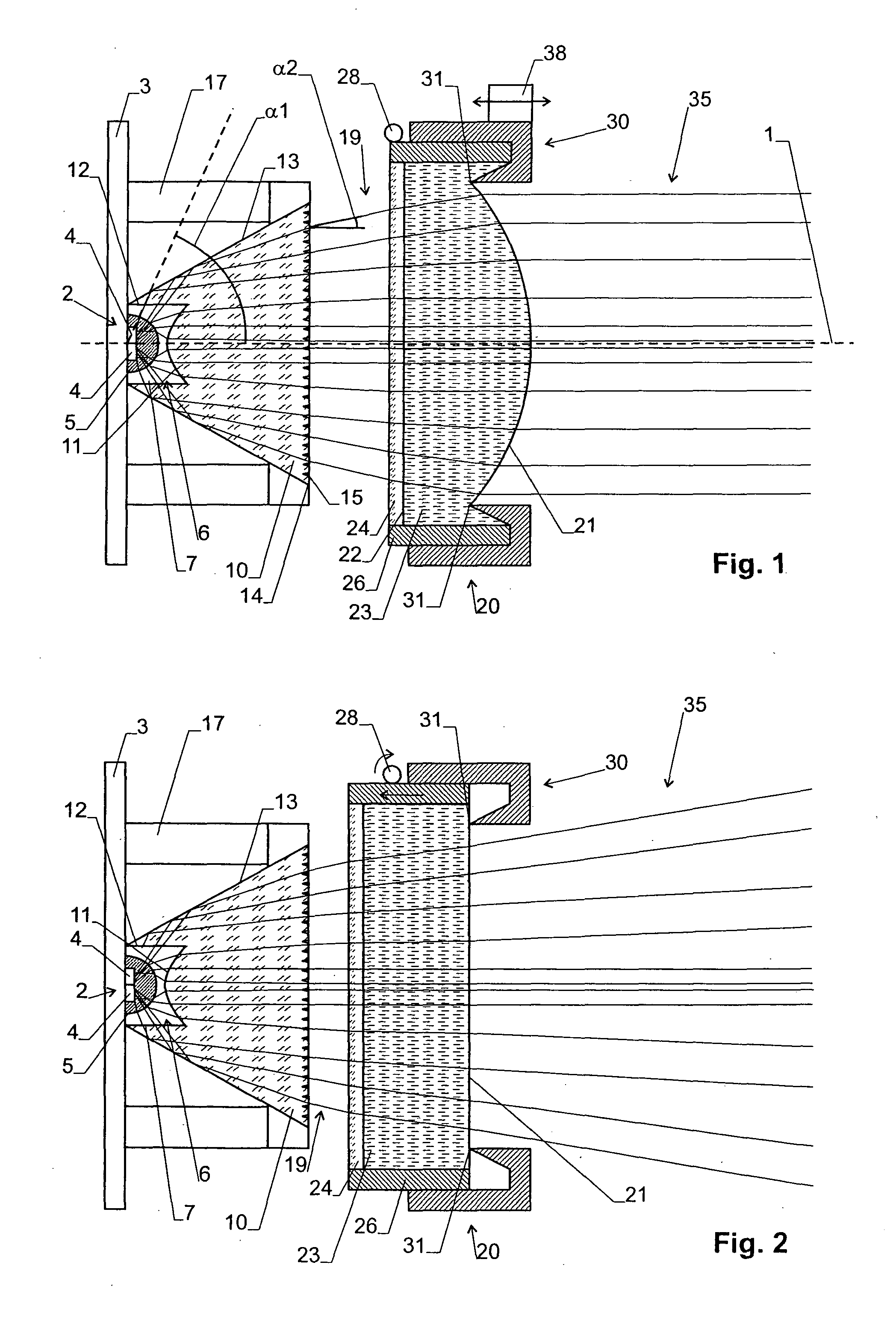
[0025]The “divergence” of a light field designates the half-angle of divergence of the light field in the far field, i.e. at a distance much larger than the wavelength from a minimum diameter of the light field.

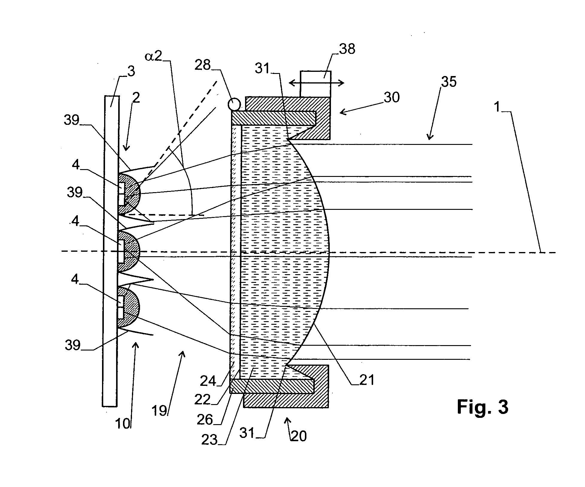
[0026]The term “divergent light field” designates a light field having a divergence exceeding 10°.

[0027]A “collimated beam” or “collimated light field” designates a light field having a divergence substantially equal to 0°.

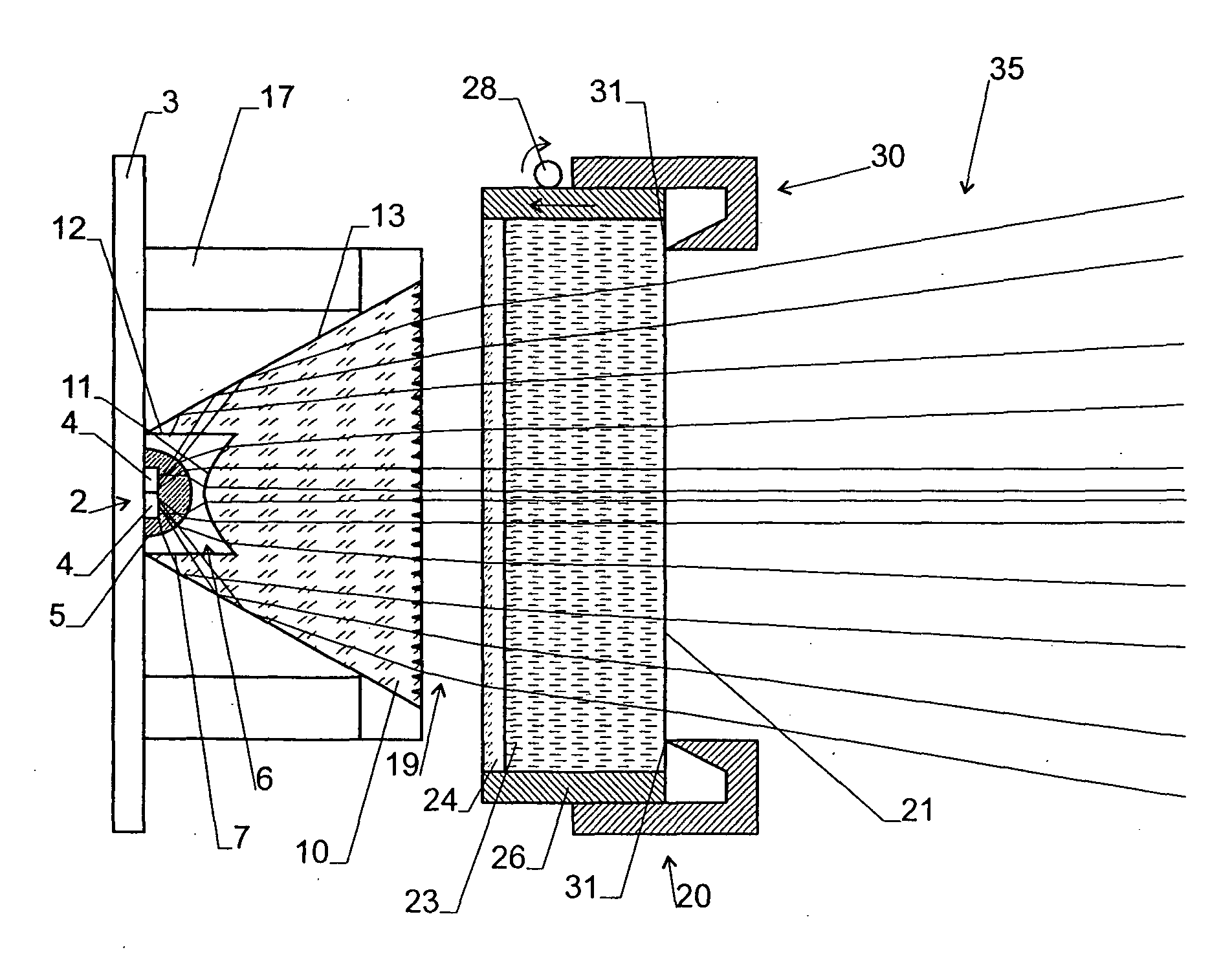
[0028]The term “axial” designates the direction parallel to the optical axis 1 of the system, the term “radial” the directions perpendicular thereto.

[0029]Illumination Source Design:

[0030]FIGS. 1 and 2 show a first embodiment of an illumination source. The illumination source is advantageously of substantially rotational symmetric design about an optical axis 1, but it may also be non-symmetric, depending on the desired geometry of the outgoing light field.

[0031]The illumination source comprises an LED light source 2, which can e.g. be mounted on...


PUM


Abstract

The illumination source has a LED light source (2) generating a first divergent light field (6). The light from the LED light source (2) is processed by a first optical element (10), in particular a first lens element, to generate a second divergent light field (19). The first divergent light field (19) is processed by a second optical element (20) having a variable lens variable focus in order to generate a third light field (35) whose divergence can be varied.

Description

TECHNICAL FIELD[0001]The invention relates to an illumination source having a LED light source and variable optics for generating a light field with variable divergence. The invention also relates to an optical assembly for such an illumination source.BACKGROUND ART[0002]For illumination purposes, a light source should advantageously generate a light field having an intensity distribution that decays continuously and monotonically in radial direction, or that is homogeneous over a certain radius.[0003]However, an LED light source, in particular an LED light source comprising a large LED or an array of LEDs, is not a point light source, and the photons emitted by its active surface are divergent and have poor spatial correlation. Hence, it is difficult to process the light field emitted by an LED light source in order to efficiently obtain a light field suited for illumination purposes.[0004]US 2006 / 0045501 describes an LED light source that generates a divergent light field. This li...

Claims


Application Information

Patent Timeline
IPC IPC(8): F21V5/00F21V7/00
CPCF21K9/00F21V5/008F21V5/04F21V7/0083F21V7/0091G02B19/0061F21V14/06F21V17/02F21Y2101/02F21Y2105/001G02B3/14F21V13/12F21K9/69F21V14/00F21Y2105/10F21Y2115/10
Inventor BUEELER, MICHAELASCHWANDEN, MANUEL
Owner OPTOTUNE CONSUMER AG
Why Eureka
Try Eureka