Auxiliary power generation circuit

a power generation circuit and auxiliary technology, applied in the direction of electric variable regulation, process and machine control, instruments, etc., can solve the problems of unnecessary loss, overheating of the integrated circuit and other related elements, and impaired stability of the auxiliary dc power, etc., and achieve the effect of simplifying the circui

Inactive Publication Date: 2013-07-04
USHIJIMA
View PDF2 Cites 6 Cited by
  • Summary
  • Abstract
  • Description
  • Claims
  • Application Information

AI Technical Summary

Benefits of technology

[0004]The primary object of the present invention is to provide a simpler circuit to generate auxiliary DC power at a smaller current.

Problems solved by technology

This causes unnecessary loss and overheat of the integrated circuit and other related elements.
Furthermore, in the event that a great variation takes place at the power input end (AC input end) the stability of the auxiliary DC power could be impaired by adopting the approaches set forth.
Even if a dedicated integrated circuit is provided to generate the auxiliary DC power, it still cannot generate the auxiliary DC power at a smaller current and could exceed safety specifications.

Method used


Image

  • Auxiliary power generation circuit
  • Auxiliary power generation circuit
  • Auxiliary power generation circuit

Examples


Embodiment Construction

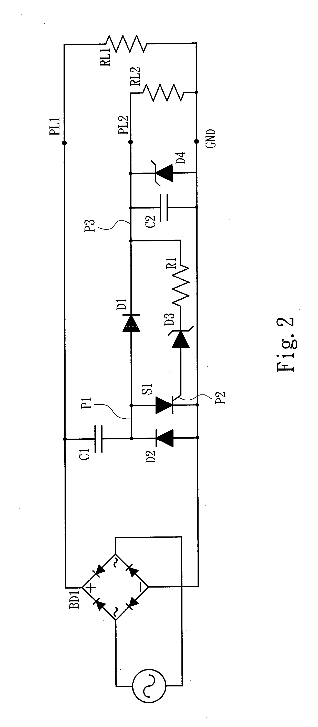
[0024]Please referring to FIG. 2, the present invention aims to provide an auxiliary power generation circuit adopted for use on a filter power circuit connected to a bridge rectification circuit BD1 which receives an external AC power to perform power conversion and includes a main duty power output end PL1 to output a main duty power and a ground end GND. The auxiliary power generation circuit includes a first voltage stabilization capacitor C 1 which is connected to the main duty power output end PL1 and has another end opposing the main duty output end PL 1 to connect to a first diode D1, and also is connected to a second voltage stabilization capacitor C2 via the first diode D1. The second voltage stabilization capacitor C2 has another end opposing the first diode D1 and connecting to the ground end GND. The first and second voltage stabilization capacitors C1 and C2 form a capacitor voltage division circuit. The first voltage stabilization capacitor C1 and first diode D1 are b...


PUM


Abstract

An auxiliary power generation circuit adopted for use on a filter power circuit includes a first voltage stabilization capacitor and a second voltage stabilization capacitor connecting to the first voltage stabilization capacitor via a first diode. The first and second voltage stabilization capacitors form a capacitor voltage division circuit. The first voltage stabilization capacitor and first diode are bridged by a first connection point which is connected to a short circuit element and a second diode with a set on current opposite to the short circuit element. The short circuit element has a control end connecting to a first Zener diode which is connected to a first resistor with a desired resistance. The first resistor is connected to a second connection point between the second voltage stabilization capacitor and first diode.

Description

FIELD OF THE INVENTION[0001]The present invention relates to an auxiliary power generation circuit and particularly to a power factor correction circuit of auxiliary DC power used on high voltage switches or integrated circuits to control LED illumination or motors.BACKGROUND OF THE INVENTION[0002]The general integrated circuits in operation while energized by electric power, often are incorporated with at least one lower voltage auxiliary DC power in addition to the main duty power. Although the auxiliary DC power can be obtained from the energized electric power mentioned above, the integrated circuits generally also contain an auxiliary power circuit to generate auxiliary DC power.[0003]The aforesaid auxiliary DC power can be generated in many ways depending on different application circuits. For instance, the auxiliary DC power for an integrated circuit to control operation of a power factor correction circuit includes an auxiliary coil wound in a choke coil. The choke coil is c...

Claims


Application Information

Patent Timeline
Patent Type & Authority Applications(United States)
IPC IPC(8): H02M3/335
CPCH02M3/33507H02M2001/0006H02M1/425H02M7/155Y02B70/10H02M1/0006
Inventor USHIJIMA, MASAKAZU
Owner USHIJIMA
Why Eureka
Try Eureka