Sandwich core material

a core material and sandwich technology, applied in the direction of wind motors with parallel air flow, liquid fuel engine components, wind energy generation, etc., can solve the problems of time-consuming and labor-intensive, and achieve the effect of reducing the total weight of the core material layer, reducing the space between the core material elements, and reducing the weight of the core material

Inactive Publication Date: 2013-07-04
SIEMENS AG
View PDF4 Cites 17 Cited by
  • Summary
  • Abstract
  • Description
  • Claims
  • Application Information

AI Technical Summary

Benefits of technology

[0033]In such a sandwich core tow, tubes, fibres, strips of foam material, either with a hollow or solid cross sectional structure, may be used. The tubes, fibres, strips may be made of a lightweight material and / or have a hollow cross sectional shape which may be filled with a lightweight material in order to reduce the weight of the core material.
[0034]In an embodiment of the method, a plurality of flexible core material elements having a substantial rectangular shape are arranged in a sheet-like form. The use of core material elements having a substantially rectangular shape results in reducing the total weight of the core material layer. The reason is that, when using elements having a substantially rectangular shape, the space between the core material elements is reduced compared to a sheet made of circular elements. As the core material is usually bonded by means of melting resins or using glue, the amount of resin or glue impregnated into the layer of core material elements is as small as possible because of the small spaces between the core material elements. Resins for the bonding may be those resins that are used in the sandwich skin(s). Hence, an improved lightweight sandwich core material and / or sandwich laminate may be prepared by this method. The sandwich laminate has an improved buckling strength because of the smooth surface provided by arranging the rectangular shaped core material elements.

Problems solved by technology

The placement of these plates in moulds has up to now been done by hand lay out and is, thus, time consuming and labour intensive.

Method used


Image

  • Sandwich core material
  • Sandwich core material
  • Sandwich core material

Examples


first embodiment

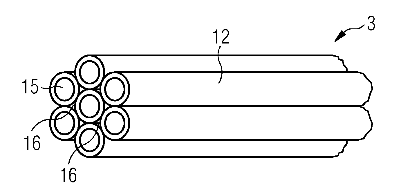
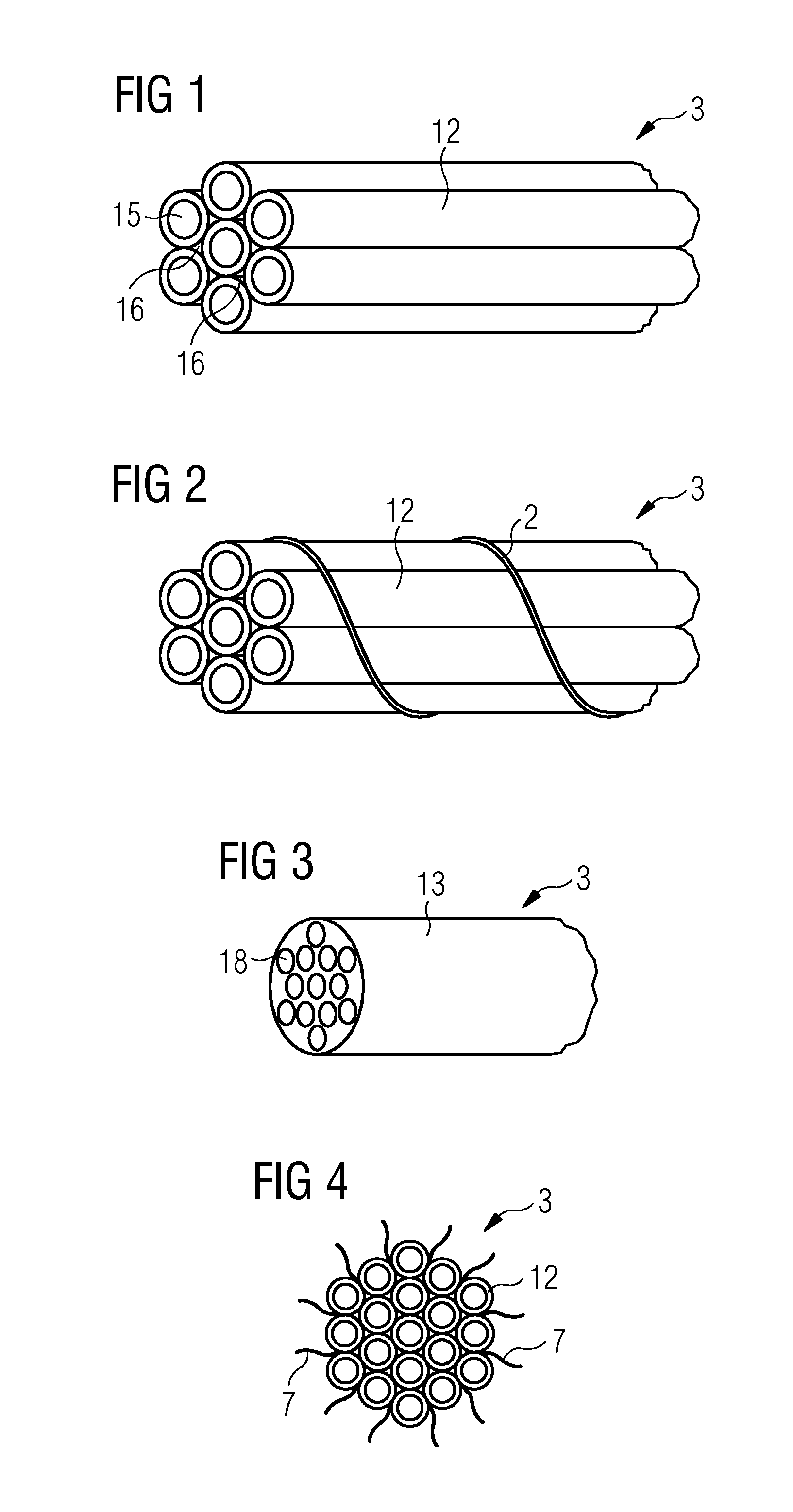
[0046]FIG. 1 shows a perspective view of a flexible core material element 3 comprising seven tubes 12 made of a polymer material. Each tube 12 is constructed with a hollow tube cross section 15. The seven tubes 12 are arranged in the form of a tow, wherein the tow comprises one tube 12 in the middle and six tubes 12 around this one middle tube 12 in the cross section of the tow. The six outer tubes 12 are bound to the tube 12 in the middle and to each adjacent tube 12 by melting the surface of the polymeric material and bonding them to each other at their respective contact points.

[0047]This tow may by used as a flexible core material element 3 because of its specific flexibility that allows winding it around a bobbin or roll for storage, transportation and delivery to a mould. Thus, the delivery into the mould may be done automatically by means of a respective robot device by using the sandwich core element delivered on a bobbin.

second embodiment

[0048]FIG. 2 shows a similar flexible core material element 3 according to a In this embodiment, seven hollow tubes 12 are arranged in a similar manner as shown in FIG. 1, but are fixed together by circumferential threads 2. Those threads 2 may be made of a plastic or fibre material which may be elastic so that it may easily be wound around the tow in a helical manner. Instead of helical threads 2, a plurality of threads wound at distinct distances from the beginning of the tow may be arranged for fixedly combining the tubes 12 to a tow. The threads 2, thus, function as external connecting means of the tubes 12.

[0049]Of course, the bonding by molten resin as explained in the first embodiment shown in FIG. 1 (an internal connection) may be combined with this external connection.

third embodiment

[0050]FIG. 3 shows a perspective view of a flexible core material element 3 according to a The core tow of this embodiment comprises a hose 13 filled with a lightweight material 18. The material of the hose 13 may be permeable to an injection resin used in order to allow an intrusion of the resin into the hose material and, thus, a fixation in the surrounding core material layer or the surrounding sandwich laminate layers. The material 18 filled into the hose 13 may be impermeable in order to avoid an intrusion of high amount of heavy weight resins. In FIG. 3, the hose 13 is filled with micro balloons 18 which are lightweight due to the high amount of air or another gas filled into the balloons. Alternatively, other lightweight materials may be used instead of the micro balloons 18, such as hollow fibres, tubes, foams or the like.

[0051]In FIG. 4, a flexible core material element 3 according to a fourth embodiment is shown in its cross section. The core tow 3 has reinforcement fibre...


PUM

PropertyMeasurementUnit
widthaaaaaaaaaa
lengthaaaaaaaaaa
thicknessaaaaaaaaaa

Abstract

A sandwich core material for a sandwich laminate is disclosed. The sandwich core material includes a number of flexible core material elements having a longitudinal structure. A flexible core material for a sandwich core material, a sandwich laminate and a wind turbine blade including such a sandwich core material are provided. In addition, the present a method of manufacturing such a sandwich core material is provided.

Description

CROSS REFERENCE TO RELATED APPLICATIONS[0001]This application claims priority of European Patent Office application No. 11195912.8 EP filed Dec. 28, 2011. All of the applications are incorporated by reference herein in their entirety.FIELD OF INVENTION[0002]The disclosure relates to a sandwich core material, in particular for sandwich laminates used in fibre reinforced plastic composites and to a core material element for such sandwich core materials. The disclosure further relates to a sandwich laminate and a wind turbine blade comprising such a sandwich core material as well as to a method of manufacturing such sandwich core material.BACKGROUND OF INVENTION[0003]In order to make lightweight and stiff constructions, sandwich constructions are often applied. Sandwich construction materials usually comprise a central lightweight core material, the sandwich core material, and one or more skin layers of composite laminate structures applied on each side of the sandwich core material, w...

Claims


Application Information

Patent Timeline
Patent Type & Authority Applications(United States)
IPC IPC(8): D01F8/00
CPCD01F8/00F03D1/0675F05B2250/12F05B2280/6012B32B5/00Y10T156/10Y10T428/2975Y10T428/2973Y10T428/2913Y10T428/13Y02E10/721Y10T428/249921Y10T156/1062Y02E10/72Y02P70/50
Inventor GROVE-NIELSEN, ERIK
Owner SIEMENS AG
Why Eureka
Try Eureka