Mosfet bridge rectifier

a rectifier and mosfet technology, applied in the direction of dc conversion, dc conversion efficiency, conversion with intermediate conversion, etc., can solve the problems of system low efficiency and higher cost, and achieve the effect of improving efficiency and controlling accurately

Inactive Publication Date: 2013-07-11
RICHTEK TECH
View PDF6 Cites 26 Cited by
  • Summary
  • Abstract
  • Description
  • Claims
  • Application Information

AI Technical Summary

Benefits of technology

[0010]A bridge rectifier according to the present invention is established by MOSFETs instead of diodes, and thus can provide a better efficiency. Moreover, the positive and

Problems solved by technology

Under heavy load condition the power loss is significant and thus makes the system low efficiency because a diode has about 0.6V forward voltage drop.
However, the existing MOSFET bridge

Method used


Image

  • Mosfet bridge rectifier
  • Mosfet bridge rectifier
  • Mosfet bridge rectifier

Examples


second embodiment

[0024]FIG. 5 is a second embodiment for the voltage detector 26 shown in FIG. 2, which identifies the voltages at the AC input terminals 28 and 30 by detecting the currents I1 and I3 of the NMOSFETs M1 and M3 to determine the detection signals Sc1 and Sc2, respectively. In this embodiment, the voltage detector 26 includes current sensors 60 and 62, comparators 46 and 48, and current sources 64 and 66. The current sensors 60 and 62 sense the currents I1 and I3 of the NMOSFETs M1 and M3 to generate current sense signals I2 and I4, respectively, and each of the current sources 64 and 66 provides a constant current Iref. When the voltage V1 of the AC input terminal 28 increases, a body diode Db1 of the NMOSFET M1 is on and thus a current I1 flows to the DC output terminal 32 from the AC input terminal 28 through the body diode Db1. The current I1 and the current sense signal I2 increase with an increase of the voltage V1. When the current sense signal I2 becomes greater than the current...

third embodiment

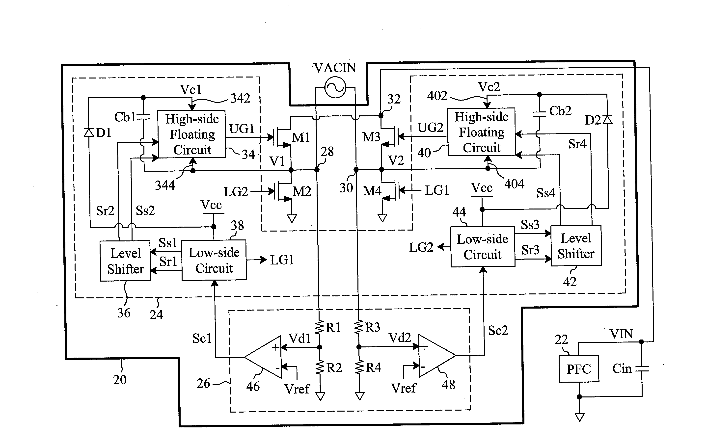
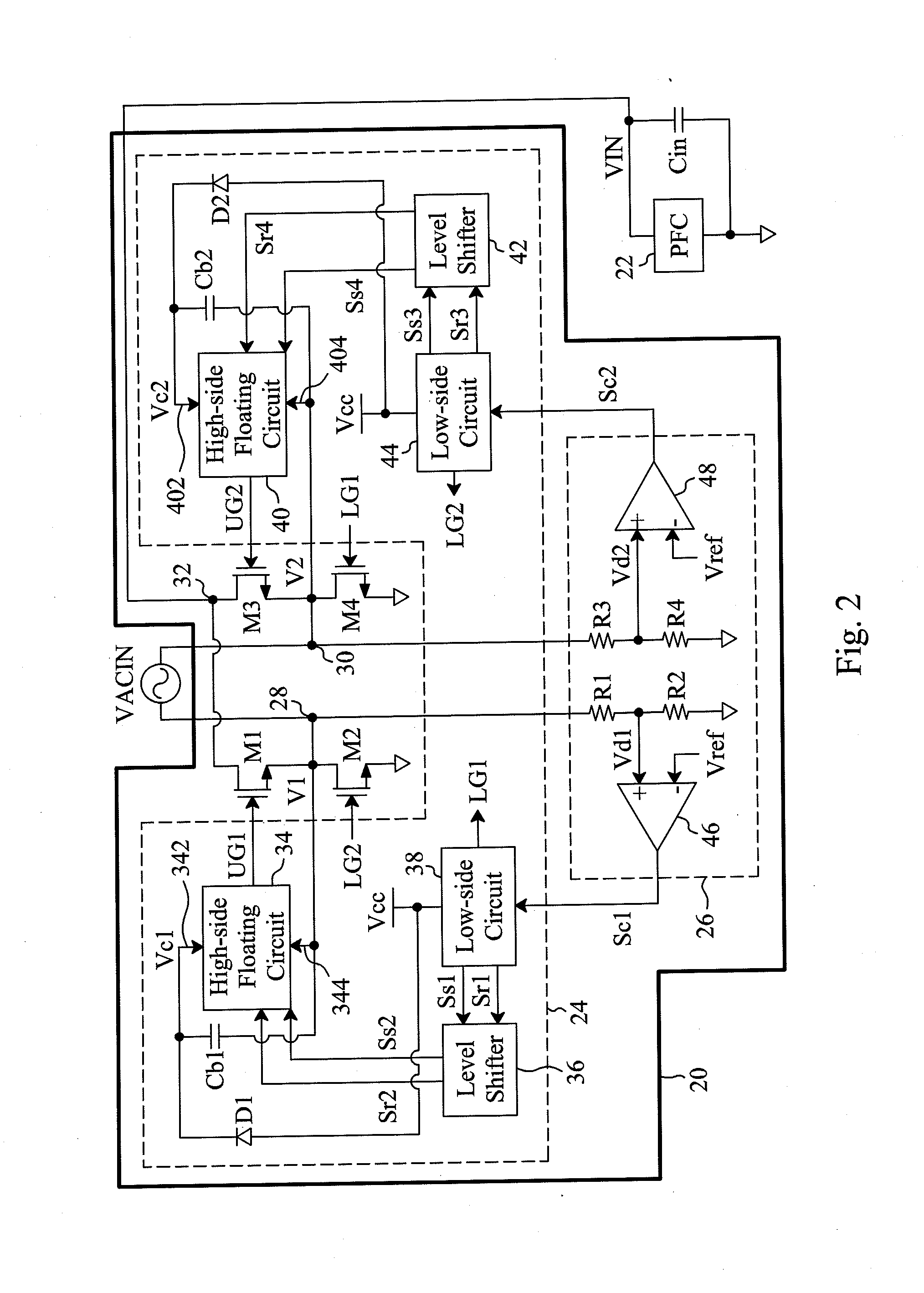
[0025]FIG. 6 is a third embodiment for the voltage detector 26 shown in FIG. 2, in which the roles of the resistors R1 and R3 shown in FIG. 2 are replaced by gate-grounded depletion-type NMOSFETs M7 and M8. When the voltages V1 and V2 are zero, the depletion-type NMOSFETs M7 and M8 are on. When the voltage V1 of the AC input terminal 28 increases, the source voltage Vd1 of the depletion-type NMOSFET M7 increases accordingly. When the voltage Vd1 reaches the threshold voltage of the depletion-type NMOSFET M7, the depletion-type NMOSFET M7 is turned off, thereby limiting the maximum value of the voltage Vd1, to prevent a high voltage from applying the voltage detector 26. When the voltage Vd1 is greater than the reference voltage Vref, the comparator 46 asserts the detection signal Sc1. Likewise, when the voltage V2 of the AC input terminal 30 increases, the voltage Vd2 increases accordingly. When the voltage Vd2 reaches the threshold voltage of the depletion-type NMOSFET M8, the depl...


PUM


Abstract

A bridge rectifier is established by MOSFETs instead of diodes. The MOSFET bridge rectifier includes a voltage detector to detect the voltages of two AC input terminals of the MOSFET bridge rectifier, for identifying the positive and negative half cycles of an AC voltage input to the MOSFET bridge rectifier, thereby accurately controlling the MOSFETs.

Description

FIELD OF THE INVENTION[0001]The present invention is related generally to a rectifier circuit and, more particularly, to a MOSFET bridge rectifier.BACKGROUND OF THE INVENTION[0002]Bridge rectifier type devices typically use diodes to convert alternating-current (AC) waveform to direct-current (DC) waveform. For example, as shown in FIG. 1, four diodes D1, D2, D3 and D4 are used to establish a bridge rectifier 10 to rectify an AC voltage VACIN into a DC voltage VIN for a power factor correction (PFC) power converter 12. Under heavy load condition the power loss is significant and thus makes the system low efficiency because a diode has about 0.6V forward voltage drop. For example, assuming that the peak current flowing through the diodes D1, D2, D3 and D4 shown in FIG. 1 is 0.2 A, a conductive diode will have a power loss of about 0.076 W.[0003]U.S. Pat. No. 7,411,768 and U.S. Pat. Publication No. 2009 / 0257259 replace the diodes in a bridge rectifier with MOSFETs to reduce the power ...

Claims


Application Information

Patent Timeline
IPC IPC(8): H02M7/219
CPCH02M7/219H02M2007/2195Y02B70/1408H02M7/2195Y02B70/10
Inventor TSENG, PEI-KAIHO, JYUN-CHETANG, CHIEN-FUCHEN, ISAAC Y.
Owner RICHTEK TECH
Why Eureka
Try Eureka