Powder-based material system with stable porosity

a material system and porosity technology, applied in the field of material systems, can solve the problems of reducing affecting the durability of tbc and metal substrate, and limited thickness of ceramic tb

Active Publication Date: 2013-07-11
SIEMENS AG
View PDF21 Cites 32 Cited by
  • Summary
  • Abstract
  • Description
  • Claims
  • Application Information

AI Technical Summary

Problems solved by technology

These voids can be beneficial for thermal insulation, but detrimental to durability of the TBC and the metal substrate.
High temperatures in the gas turbine environment can cause changes in the properties of the ceramic TBC, including further sintering, that can lead to spalling of the TBC.
Additionally, the thickness of a ceramic TBC is limited due to the mismatch of processing shrinkage between the ceramic coating and the metallic substrate and from differential thermal expansion during operation cycles.
This thinness limits the amount of oxidation protection, abrasion protection, and insulation that can be provided by a TBC, and limits its life.
However, these methods provide a non-chemical bond with limited durability.
However, the sintering shrinkage of typical metal powders is about 6%, while that of typical ceramic powders is about 1%, and ceramics require much higher sintering temperatures than metals.
These sintering disparities, plus different thermal expansion rates and different mechanisms of bonding between atoms, make a stress free bonding of ceramics to metals very difficult under normal circumstances.
Operation at such high temperatures causes continued densification of the ceramic material over time.

Method used


Image

  • Powder-based material system with stable porosity
  • Powder-based material system with stable porosity
  • Powder-based material system with stable porosity

Examples


Embodiment Construction

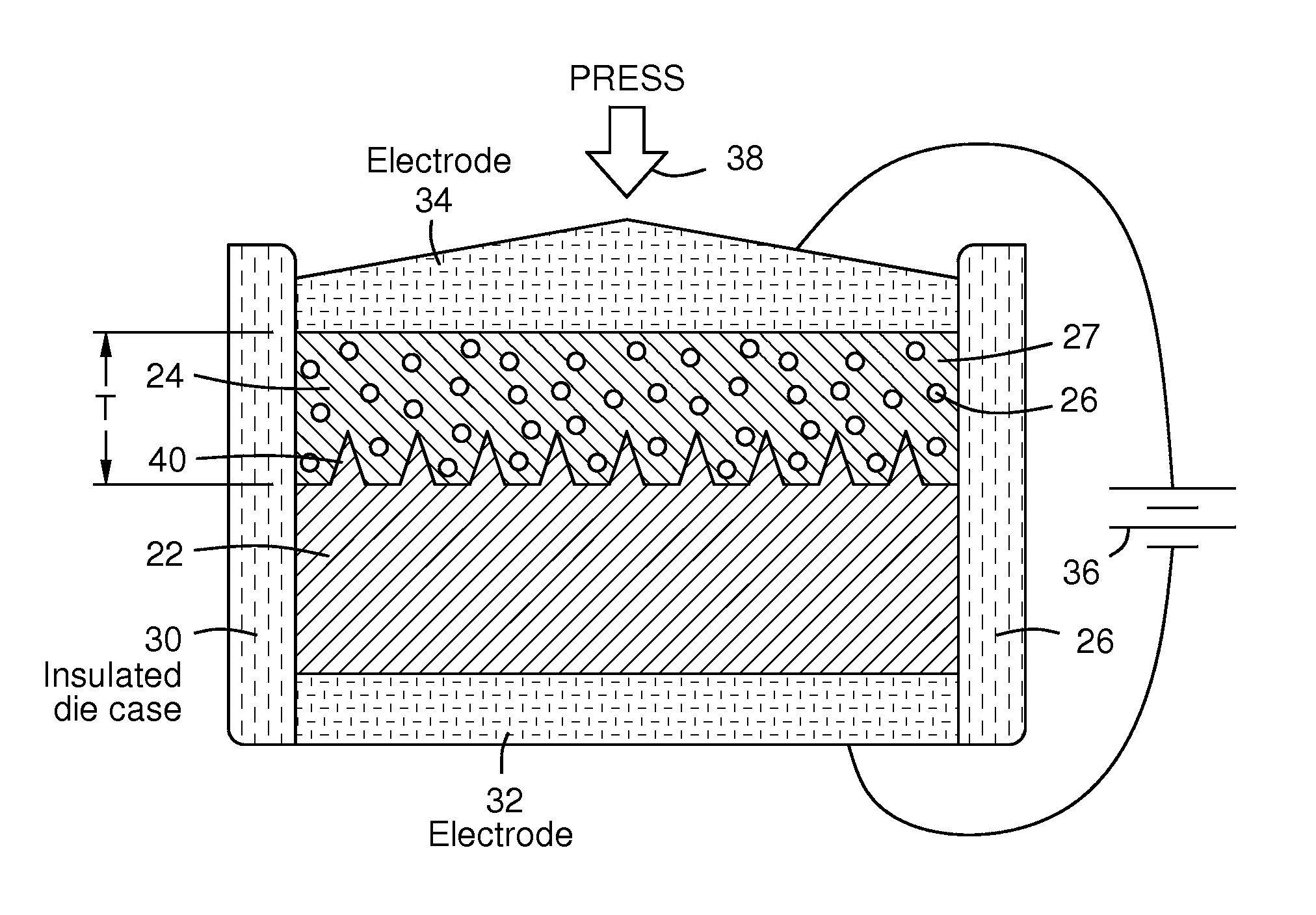
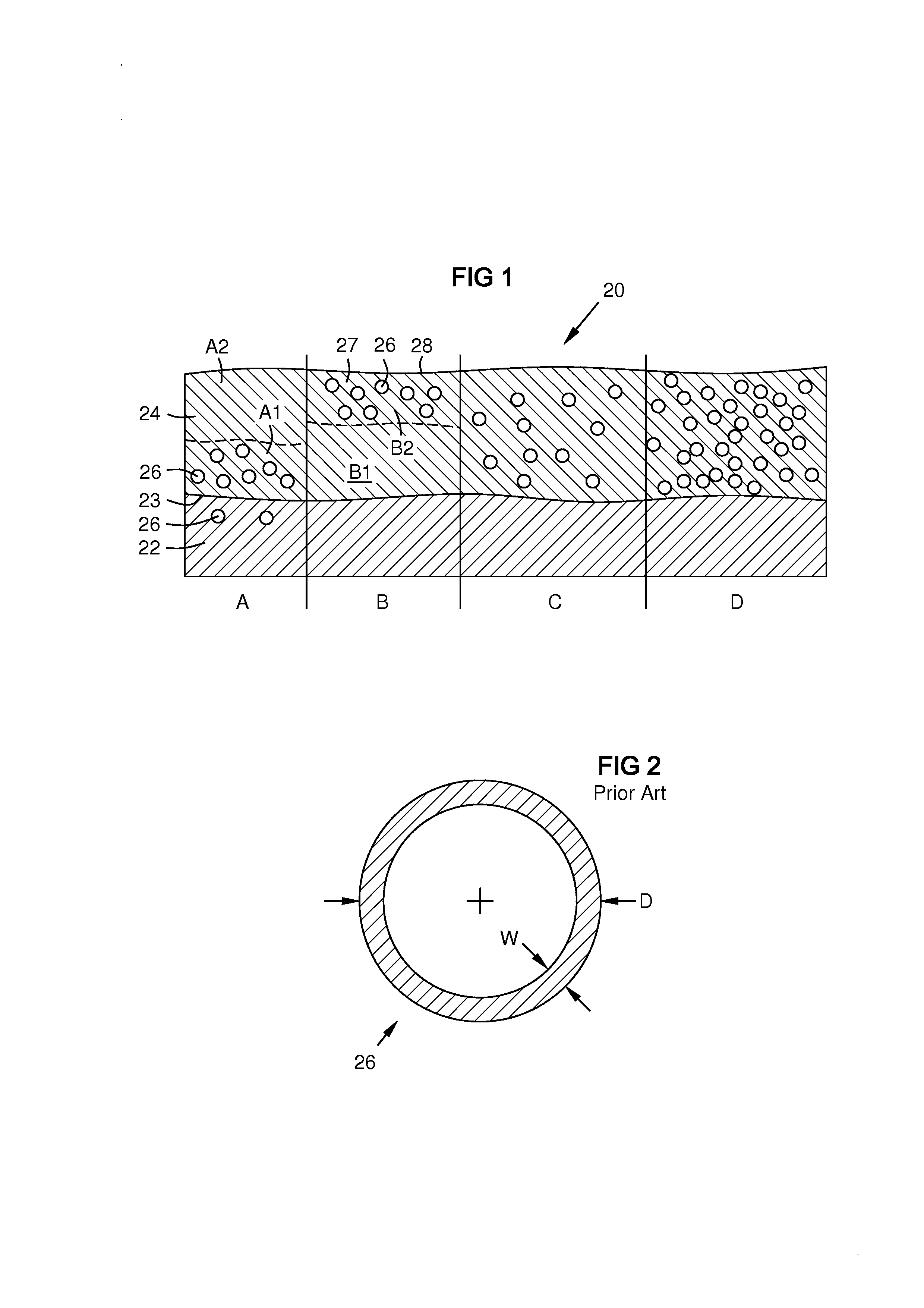
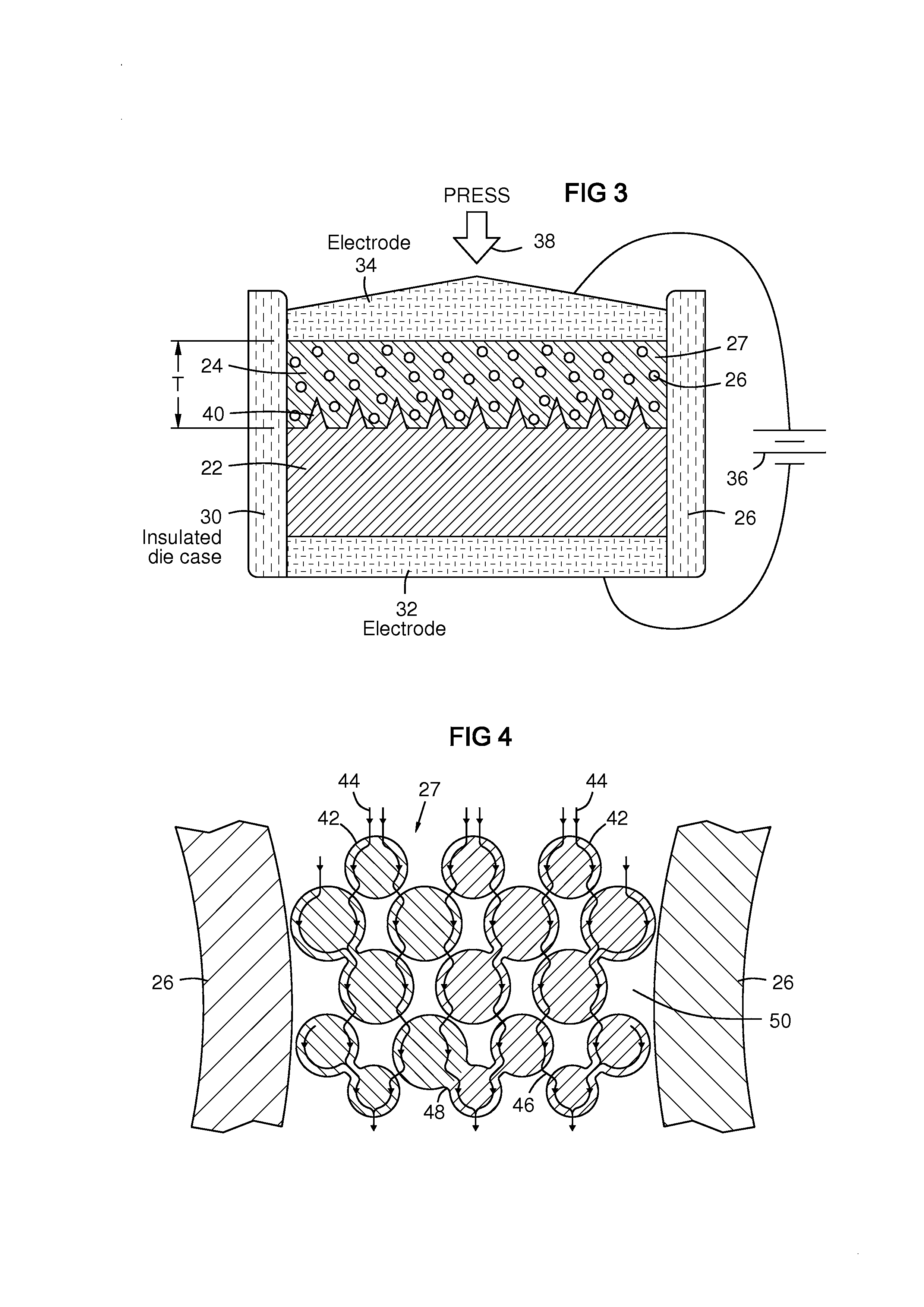
[0014]The present invention provides a sintered powder structure that is stable during high temperature operation (i.e. it behaves like a fully dense material not subject to further sintering), yet it contains a known and stable amount of porosity. The inventors have recognized that if a powder-based material system could be formed with stable hollow shapes such as hollow ceramic spheres having fully dense walls in a fully dense ceramic matrix, the material system would provide a specific intrinsic volume fraction of voids, and would not further sinter. This would prevent a further change of porosity or a change in system properties during subsequent high temperature operational conditions. Such a material system with temperature-stable porosity enables an abradable coating that can be used in otherwise non-reachable temperature regimes, for example enabling an abradable ceramic material that can be used at operating temperatures up to 1500° C. in one embodiment. Such a material sys...


PUM

PropertyMeasurementUnit
diameteraaaaaaaaaa
aspect ratioaaaaaaaaaa
shrinkageaaaaaaaaaa

Abstract

A powder-based material system having an intrinsic and stable degree of porosity provided by hollow ceramic spheres (26) in a fully dense matrix (27). A substrate (22) is formed from a metal powder (70), and may be partially sintered (60). A layer (24) of ceramic powder is arranged on the substrate including the pre-sintered hollow ceramic spheres plus a proportion of nano-sized ceramic particles effective to reduce the layer sintering temperature and to increase the sintering shrinkage of the layer to approximate that of the metal substrate during subsequent co-sintering. The substrate and layer are then co-sintered (61), such as with spark plasma sintering (32, 34, 36), at a temperature and for a duration to fully densify the ceramic powder matrix around the hollow spheres, thereby producing a metal / ceramic material system with low interface stress and with stable porosity during operational temperatures in a gas turbine engine.

Description

FIELD OF THE INVENTION[0001]The invention relates to material systems for components in the hot gas path of a gas turbine, and particularly to methods and compositions for fabricating a metal substrate with a ceramic thermal barrier layer.BACKGROUND OF THE INVENTION[0002]Metal components in the working gas path in a gas turbine engine may have a ceramic thermal barrier coating (TBC). Random voids can form in the TBC from sintering shrinkage during processing. These voids can be beneficial for thermal insulation, but detrimental to durability of the TBC and the metal substrate. The amount and size of voids formed and the resulting porosity are not controlled variables. High temperatures in the gas turbine environment can cause changes in the properties of the ceramic TBC, including further sintering, that can lead to spalling of the TBC. Additionally, the thickness of a ceramic TBC is limited due to the mismatch of processing shrinkage between the ceramic coating and the metallic sub...

Claims


Application Information

Patent Timeline
Patent Type & Authority Applications(United States)
IPC IPC(8): B05D3/06B32B3/10B32B3/00B05D3/02B32B7/02
CPCB22F3/1112Y10T428/24496B22F7/002B22F3/105B22F3/1017B32B7/02B32B3/00B32B3/10C04B37/021C04B2235/34C04B2235/5436C04B2235/5454C04B2235/5472C04B2235/666C04B2235/9607C04B2237/343C04B2237/348C04B2237/403C04B2237/405C04B2237/64C04B2237/704B82Y30/00Y10T428/24942B22F5/009B32B5/30B32B3/26B32B2264/105B32B2264/107B32B2307/304Y10T428/249969B22F7/008
Inventor MERRILL, GARY B.SCHILLIG, CORA
Owner SIEMENS AG
Why Eureka
Try Eureka