Hydrogen production device and method for producing hydrogen

a production device and hydrogen technology, applied in the direction of electrolytic organic production, instruments, oxygen/ozone/oxide/hydroxide, etc., can solve the problems of difficult compensation, low energy use efficiency, and increased energy consumption of power generation facilities, so as to increase the amount increase the light use efficiency, and increase the effect of light incident on the photoelectric conversion portion

Active Publication Date: 2013-07-18
SHARP KK
View PDF4 Cites 15 Cited by
  • Summary
  • Abstract
  • Description
  • Claims
  • Application Information

AI Technical Summary

Benefits of technology

[0017]According to the present invention, a potential difference can be generated between the first area and the second area on the back surface of the photoelectric conversion portion by causing light to be incident on the light-receiving surface of the photoelectric conversion portion. As a result, a potential difference can also be generated between the first electrolysis electrode that is electrically connected to the first area and the second electrolysis electrode that is electrically connected to the second area. By bringing an electrolyte solution into contact with the first electrolysis electrode and the second electrolysis electrode between which the potential difference is generated, H2 can be generated from the electrolyte solution in one of the first electrolysis electrode and the second electrolysis electrode and O2 can be generated from the electrolyte solution in the other electrolysis electrode. The generated H2 is collected, thus producing hydrogen.
[0018]According to the present invention, since the hydrogen generation portion and the oxygen generation portion are formed on the back surface of the photoelectric conversion portion, light can enter the light-receiving surface without passing through the electrolyte solution, thus preventing the incident light from being absorbed or scattered by the electrolyte solution. Consequently, the amount of light incident on the photoelectric conversion portion can be increased to increase the light use efficiency.
[0019]In addition, according to the present invention, since the hydrogen generation portion and the oxygen generation portion are formed on the back surface of the photoelectric conversion portion, light incident on the light-receiving surface is not absorbed or scattered by the hydrogen generation portion and the oxygen generation portion, and hydrogen and oxygen generated therefrom. Consequently, the amount of light incident on the photoelectric conversion portion can be increased to increase the light use efficiency.
[0020]According to the present invention, since the hydrogen generation portion and the oxygen generation portion are formed on the back surface of the photoelectric conversion portion, the light-receiving surface of the photoelectric conversion portion can be provided on most of a surface of the hydrogen production device, the surface receiving light. Consequently, the light use efficiency can be further increased.
[0021]According to the present invention, since the photoelectric conversion portion, the hydrogen generation portion, and the oxygen generation portion are provided in the same device, the hydrogen production cost can be reduced as compared with an existing combination of a solar cell and a water electrolysis device.
[0022]According to the present invention, a potential difference is generated between the first area and the second area on the back surface as a result of reception of light by the photoelectric conversion portion. Therefore, the first area and the second area can be easily electrically connected to the first electrolysis electrode and the second electrolysis electrode, respectively, which are provided on the back surface of the photoelectric conversion portion, and the production cost can be reduced. In the case where a potential difference is generated between a light-receiving surface and a back surface as a result of reception of light by a photoelectric conversion portion, the area of the light-receiving surface of the photoelectric conversion portion may be decreased because the light-receiving surface is electrically connected to a first electrolysis electrode or a second electrolysis electrode. In contrast, according to the present invention, since a potential difference is generated between the two areas on the back surface of the photoelectric conversion portion, a larger area of the light-receiving surface of the photoelectric conversion portion can be ensured to increase the amount of light received. Furthermore, since a conduction distance between the photoelectric conversion portion and the first electrolysis electrode or the second electrolysis electrode can be made small, the internal resistance can be further reduced.

Problems solved by technology

Although many solar cell techniques and techniques for utilizing solar heat have already been practically used, the energy use efficiency is still low and the cost for producing electricity and heat is still high.
Furthermore, although these energy forms such as electricity and heat can be used for compensating for a short-term energy fluctuation, they have problems in that, for example, it is very difficult to compensate for a long-term fluctuation such as a seasonal fluctuation, and the operating ratio of power generation facilities may be decreased with an increase in the amount of energy.

Method used


Image

  • Hydrogen production device and method for producing hydrogen
  • Hydrogen production device and method for producing hydrogen
  • Hydrogen production device and method for producing hydrogen

Examples


Embodiment Construction

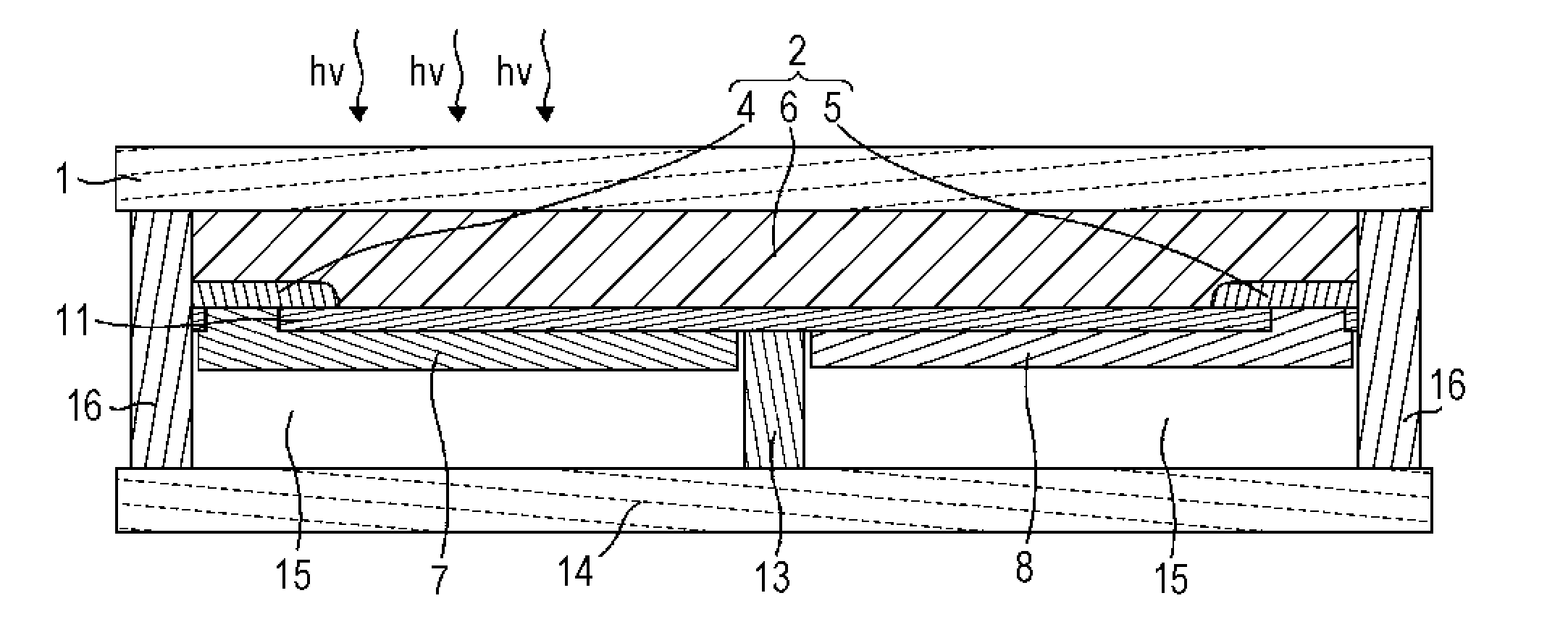
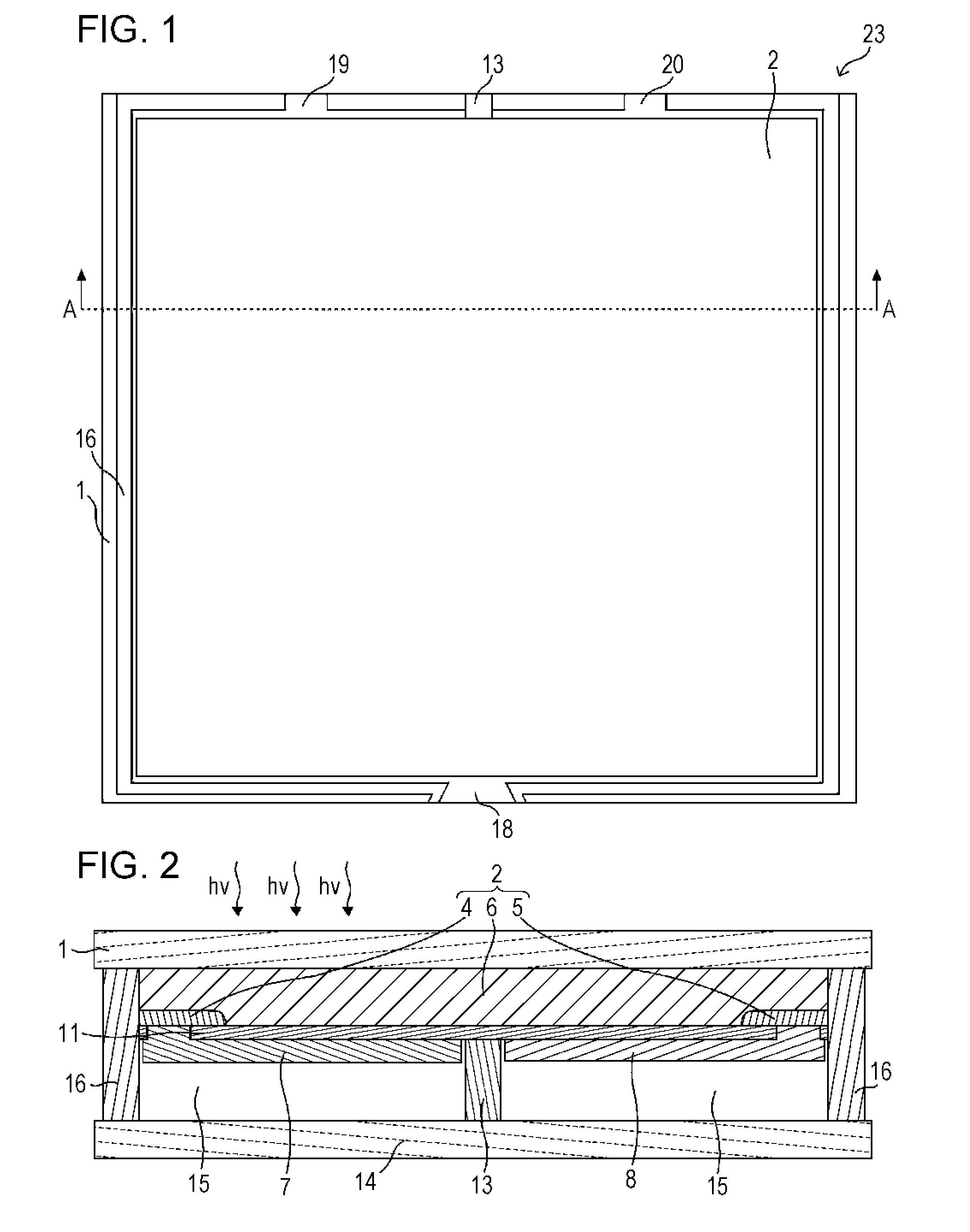
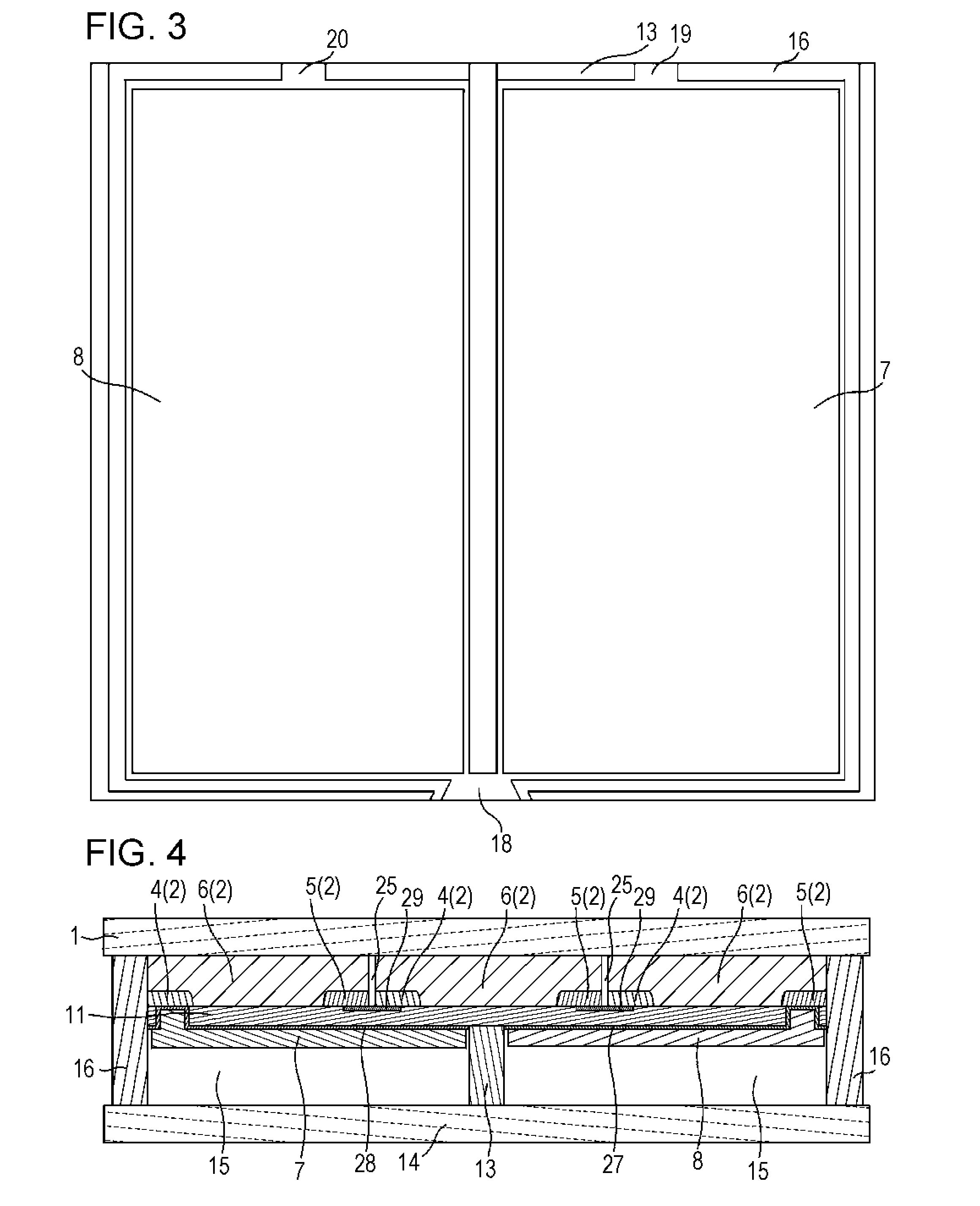
[0031]A hydrogen production device of the present invention includes a photoelectric conversion portion having a light-receiving surface and a back surface, a first electrolysis electrode provided on the back surface, and a second electrolysis electrode provided on the back surface. As a result of reception of light by the photoelectric conversion portion, a potential difference is generated between a first area on the back surface and a second area on the back surface, the first area becomes electrically connected to the first electrolysis electrode, and the second area becomes electrically connected to the second electrolysis electrode. When the first electrolysis electrode and the second electrolysis electrode contact an electrolyte solution, the first electrolysis electrode forms a hydrogen generation portion that generates H2 from the electrolyte solution using an electromotive force generated as a result of reception of light by the photoelectric conversion portion and the sec...


PUM


Abstract

A hydrogen production device of the present invention includes a photoelectric conversion portion having a light-receiving surface and a back surface, a first electrolysis electrode provided on the back surface, and a second electrolysis electrode provided on the back surface. As a result of reception of light by the photoelectric conversion portion, a potential difference is generated between a first area on the back surface and a second area on the back surface, the first area becomes electrically connected to the first electrolysis electrode, and the second area becomes electrically connected to the second electrolysis electrode. When the first electrolysis electrode and the second electrolysis electrode contact an electrolyte solution, the first electrolysis electrode forms a hydrogen generation portion that generates H2 from the electrolyte solution using an electromotive force generated as a result of reception of light by the photoelectric conversion portion and the second electrolysis electrode forms an oxygen generation portion that generates O2 from the electrolyte solution using the electromotive force.

Description

TECHNICAL FIELD[0001]The present invention relates to a hydrogen production device and a method for producing hydrogen.BACKGROUND ART[0002]Recently, use of renewable energy has been desired from the standpoint of depletion of fossil fuel resources, suppression of greenhouse gas emissions, etc. Renewable energy is generated from various energy sources such as sunlight, hydraulic power, wind power, geothermal heat, tidal power, and biomass. Among these renewable energy sources, sunlight has a large amount of energy that can be utilized and has relatively small geographic restrictions as compared with other renewable energy sources. Thus, a technique for efficiently generating usable energy from sunlight has been desired to be developed and widely used at an early stage.[0003]Examples of the form of usable energy generated from sunlight include electrical energy produced by using a solar cell or a solar thermal turbine, thermal energy obtained by collecting solar energy in a heating me...

Claims


Application Information

Patent Timeline
Patent Type & Authority Applications(United States)
IPC IPC(8): C25B1/04
CPCC25B1/003C25B1/04H01L31/048C01B13/0207Y02E60/366Y02E60/364C01B3/042Y02E10/50C25B1/55Y02E60/36
Inventor YOSHIDA, AKIHITOSATA, SHUNSUKEKAGA, MASAKI
Owner SHARP KK
Why Eureka
Try Eureka