Method of forming an optical device

a technology of optical devices and optical components, applied in the direction of converting sensor output, separating media, instruments, etc., can solve the problems of significant worsening of the signal to noise ratio that is obtainable by readhead measurement on the phase scale, affecting the reflectivity of the readhead, and increasing the signal to noise ratio. , to achieve the effect of reducing the transfer of material

Inactive Publication Date: 2013-07-18
RENISHAW PLC
View PDF15 Cites 44 Cited by
  • Summary
  • Abstract
  • Description
  • Claims
  • Application Information

AI Technical Summary

Benefits of technology

[0031]The laser beam may have an intensity above a threshold intensity thereby to reduce the transfer of material to the first part of the target area in comparison to the transfer of material to the second part of the target area. By providing such an

Problems solved by technology

Variations in the height of the marks, or the depths of the wells, or the presence of significant roughness on the surface can cause a significant worsening in signal to noise ratios that are obtainable by readhead measurements on the phase scale.
However such laser ablation techniques can result in the wells having rough surfaces, affecting their reflectivity and increasing signal to noise ratio.
Furthermore, if significant quantities of material are ablated from the surface it has been f

Method used


Image

  • Method of forming an optical device
  • Method of forming an optical device
  • Method of forming an optical device

Examples


Embodiment Construction

[0052]Embodiments of the invention are now described, by way of non-limiting example, and are illustrated in the following figures, in which:

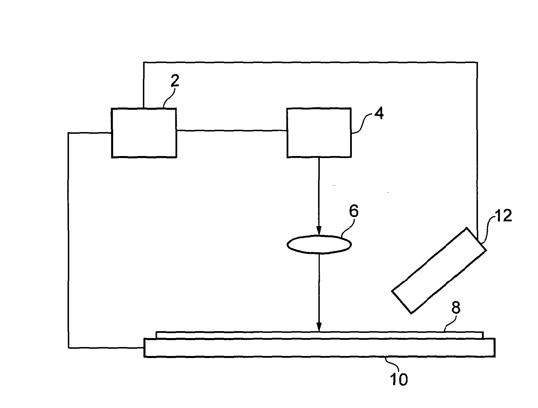
[0053]FIG. 1 is an illustration of an apparatus for forming an optical device according to an embodiment;

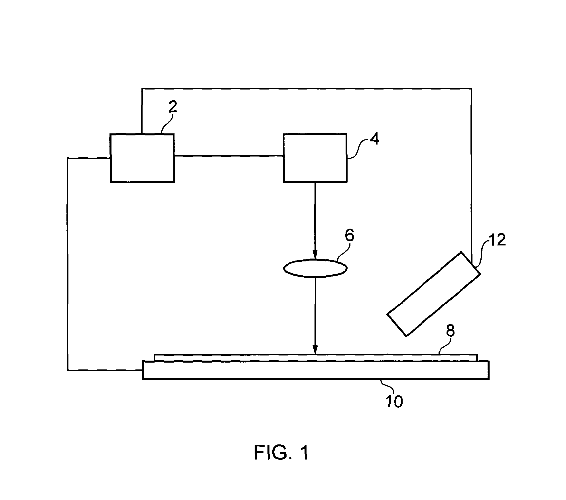
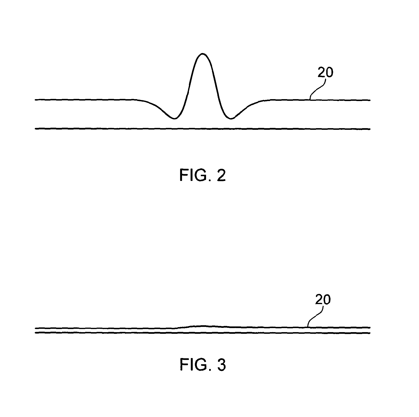
[0054]FIGS. 2 and 3 are schematic illustrations of the surface of a sample showing the profile of the surface after application of laser beam to a target region

[0055]FIG. 4 is a schematic illustration of the surface of a sample showing the profile of the surface after application of a laser beam to a plurality of target regions to form a desired device profile;

[0056]FIG. 5 is a schematic illustration of the surface of a sample showing the profile of the surface after application of a laser beam having an intensity in a central part of the beam that is greater than a threshold below which a central peak is formed;

[0057]FIG. 6 is a schematic illustration of the surface of a sample showing the profile of the surface after application of a laser...


PUM

PropertyMeasurementUnit
Temperatureaaaaaaaaaa
Lengthaaaaaaaaaa
Compositionaaaaaaaaaa

Abstract

A method of forming an optical device comprises applying a laser beam to a target area of the surface so as to selectively heat material of the surface thereby to provide transfer of material due to a surface tension gradient, wherein the surface is such that, when liquid, parts of the surface at higher temperatures have a higher surface tension than adjacent parts of the surface at lower temperatures.

Description

FIELD OF THE INVENTION[0001]The present invention relates to the formation of optical devices, for example the formation of optical devices by application of a laser beam to a surface to alter the optical properties of the surface.[0002]The invention has particular application to, but is not limited to, the production of phase scale devices or other metrological devices.BACKGROUND TO THE INVENTION[0003]Many different techniques for producing optical devices on a surface are known. For example, there are various well known techniques for producing metrological scales, for example phase scales or amplitude scales.[0004]Amplitude scales usually comprise a surface that includes features that determine the amplitude of light that, in operation, is received by a readhead from the scale. For example, a reflective amplitude scale can include a sequence of reflective and non-reflective lines formed at accurately determined positions on the surface. As the readhead is moved over the surface i...

Claims


Application Information

Patent Timeline
IPC IPC(8): B23K26/00B23K26/12
CPCB23K26/0078B23K26/126G01D5/34707B23K26/0051B23K26/0081B23K26/4065B23K26/0012B23K26/0036B23K26/367B23K26/4005B23K26/401B23K26/0009B23K26/354B23K26/0006B23K26/3584B23K26/364B23K26/40B23K2101/35B23K2103/05B23K2103/08B23K2103/26B23K2103/42B23K2103/50
Inventor WESTON, NICHOLAS JOHNHAND, DUNCAN PAULGIET, STEPHANIEARDRON, MARCUS
Owner RENISHAW PLC
Why Eureka
Try Eureka