Medical treatment system and methods using a plurality of fluid lines

a treatment system and fluid line technology, applied in the field of medical treatment system and method using a plurality of fluid lines, can solve the problems of dampening the acceptance of apd as an alternative by the general population, unable to meet the requirements of capd or other methods, etc., to achieve the effect of reducing noise, compact system, and reducing pneumatic pressure or vacuum

Active Publication Date: 2013-07-18
DEKA PROD LLP
View PDF2 Cites 133 Cited by
  • Summary
  • Abstract
  • Description
  • Claims
  • Application Information

AI Technical Summary

Benefits of technology

[0031]In another embodiment, the tubing state detector may be arranged to detect whether there is liquid present in the tubing segment, e.g., whether the patient line is properly primed for use. For example, the detector may include a third light emitter having a third optical axis that is arranged at an oblique angle relative to the sensor optical axis. The oblique angle may be between 90 and 180 degrees, e.g., about 110-120 degrees. The optical sensor and third light emitter may be arranged such that with a tubing segment in the space and the tubing segment containing no liquid, a light level detected by the optical sensor may be over about 150% of a calibration light level detected with no tubing segment in the space. In addition, with a tubing segment in the space and containing liquid, the optical sensor may detect a light level from the third light emitter that is less than about 125% of the calibration light level. Thus, the optical sensor and third light emitter may be arranged such that with a tubing segment in the space and the tubing segment containing no liquid, a light level detected by the optical sensor may be over a threshold level, and with a tubing segment in the space and the tubing segment containing liquid, a light level detected by the optical sensor is less than the threshold level. This arrangement may allow the detector to determine whether liquid is contained in the patient line, e.g., whether the patient line is properly primed. In one embodiment, the third light emitter and the optical sensor may be arranged such that the optical sensor receives light from the third light emitter both when a tubing segment in the space is filled with liquid and when a tubing segment in the space is empty of liquid. Thus, the presence or absence of liquid in the tubing segment may be determined based on a detected light intensity rather than the presence or absence of light. This may help the system avoid false condition detection that might result if the detector were to use the absence of detected light to indicate a condition, such as the presence of liquid in the tubing segment. That is, since the optical sensor detects light from the third light emitter regardless of the presence of liquid, the optical sensor may be able to determine whether the third light emitter is operating properly (or at all). The space in which the tubing segment is held may be arranged to receive and hold the tubing segment, which may have a cylindrical outer surface, without substantially deforming the tubing segment. Thus, the detector may operate without deforming the tubing segment, thereby avoiding potential problems such as pinching, reduced flow in the tubing segment, etc.
[0102]In another embodiment, the occluder includes first and second opposed occluding members pivotally connected to each other, a tube contacting member connected to, or comprising at least a portion of, at least one of the first and second occluding members, and a force actuator constructed and positioned to apply a force to at least one of the first and second occluding members. Application of the force by the force actuator may cause the tube contacting members to move between a tube occluding and an open position. The occluder may include a release member configured and positioned to enable an operator to manually move the tube contacting member from the tube occluding position to the open position even with no force applied to the occluding member by the force actuator. The force actuator may apply a force sufficient to bend both the first and second occluding members, so that upon application of the force by the force actuator to bend the first and second occluding members, the tube contacting member may move between a tube occluding and an open position. The occluding members may be spring plates pivotally connected together at opposite first and second ends, and the tube contacting member may be a pinch head connected to the spring plates at the first ends, while the second ends of the spring plates may be affixed directly or indirectly to a housing to which the occluder is connected. In one embodiment, the force actuator comprises an inflatable bladder positioned between the first and second occluding members. The force actuator may increase a distance between the first and second occluding members in a region where the first and second occluding members are in opposition so as to move the tube contacting member between a tube occluding and an open position. In one embodiment, the force actuator may bend one or both of the occluding members to move the tube contacting member from a tube occluding position to an open position.

Problems solved by technology

IPD can also be used when a patient requires PD, but cannot undertake the responsibilities of CAPD or otherwise do it at home.
Still, the complexity and size of past machines and associated disposables for various APD modalities have dampened widespread patient acceptance of APD as an alternative to manual peritoneal dialysis methods.

Method used


Image

  • Medical treatment system and methods using a plurality of fluid lines
  • Medical treatment system and methods using a plurality of fluid lines
  • Medical treatment system and methods using a plurality of fluid lines

Examples


Embodiment Construction

[0216]Although aspects of the invention are described in relation to a peritoneal dialysis system, certain aspects of the invention can be used in other medical applications, including infusion systems such as intravenous infusion systems or extracorporeal blood flow systems, and irrigation and / or fluid exchange systems for the stomach, intestinal tract, urinary bladder, pleural space or other body or organ cavity. Thus, aspects of the invention are not limited to use in peritoneal dialysis in particular, or dialysis in general.

[0217]APD System

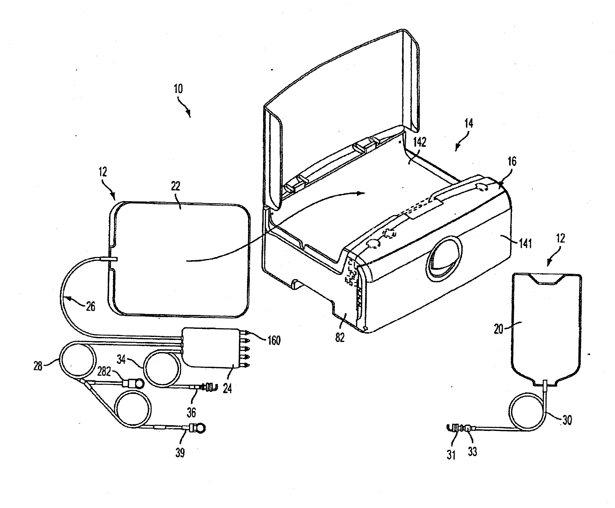
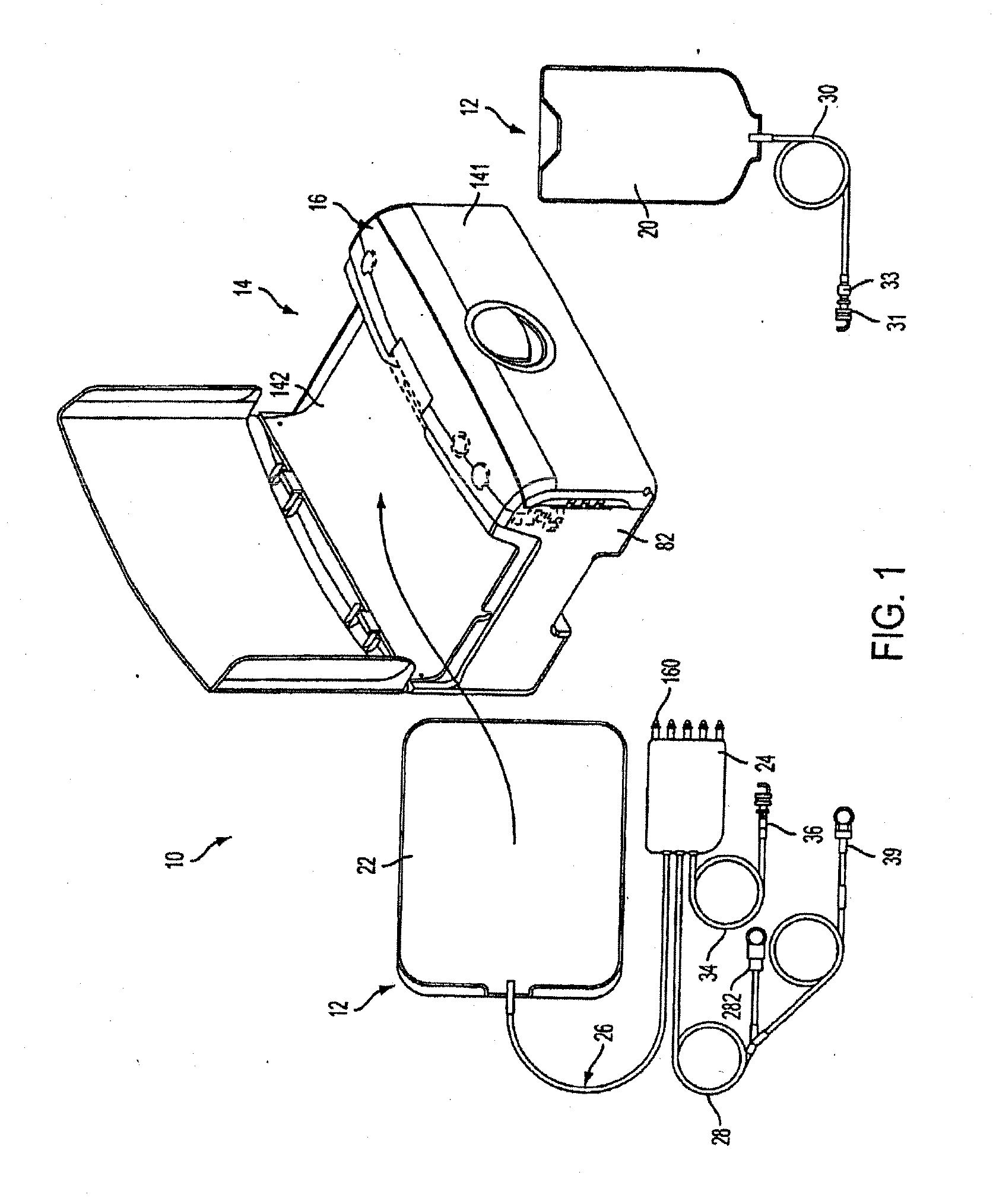
[0218]FIG. 1 shows an automated peritoneal dialysis (APD) system 10 that may incorporate one or more aspects of the invention. As shown in FIG. 1, for example, the system 10 in this illustrative embodiment includes a dialysate delivery set 12 (which, in certain embodiments, can be a disposable set), a cycler 14 that interacts with the delivery set 12 to pump liquid provided by a solution container 20 (e.g., a bag), and a control system 16 (e.g...


PUM


Abstract

A medical treatment system, such as peritoneal dialysis system, may include control and other features to enhance patient comfort and ease of use. For example, a peritoneal dialysis system may include a control system that can adjust the volume of fluid infused into the peritoneal cavity to prevent the intraperitoneal fluid volume from exceeding a pre-determined amount. The control system can adjust by adding one or more therapy cycles, allowing for fill volumes during each cycle to be reduced. The control system may continue to allow the fluid to drain from the peritoneal cavity as completely as possible before starting the next therapy cycle. The control system may also adjust the dwell time of fluid within the peritoneal cavity during therapy cycles in order to complete a therapy within a scheduled time period. The cycler may also be configured to have a heater control system that monitors both the temperature of a heating tray and the temperature of a bag of dialysis fluid in order to bring the temperature of the dialysis fluid rapidly to a specified temperature, with minimal temperature overshoot.

Description

[0001]This application is a continuation in part of U.S. application Ser. No. 13 / 178,191, filed Jul. 7, 2011, which claims the benefit of and U.S. Provisional application No. 61 / 362,259, filed Jul. 7, 2010.[0002]This application is a continuation in part of U.S. application Ser. No. 12 / 864,357, filed Jul. 23, 2010, which is a national stage of PCT application PCT / US2009 / 000440, filed Jan. 23, 2009, which claims the benefit of U.S. Provisional application No. 61 / 011,967, filed Jan. 23, 2008 and U.S. Provisional application No. 61 / 058,469, filed Jun. 3, 2008.[0003]This application is a continuation in part of U.S. application Ser. No. 12 / 864,378, filed Jul. 23, 2010, which is a national stage of PCT application PCT / US2009 / 000436, filed Jan. 23, 2009, which claims the benefit of U.S. Provisional application No. 61 / 011,967, filed Jan. 23, 2008 and U.S. Provisional application No. 61 / 058,469, filed Jun. 3, 2008.[0004]This application is a continuation in part of U.S. application Ser. No....

Claims


Application Information

Patent Timeline
Patent Type & Authority Applications(United States)
IPC IPC(8): A61M1/28
CPCG01V8/20A61M2205/12A61M2205/13A61M1/3656A61M2205/3306A61M1/28A61M1/288A61M2205/14A61M1/166A61M1/282A61M2205/8206A61M1/155A61M1/1565A61M1/159A61M1/1522A61M1/1561
Inventor SCARPACI, JACOB W.BRYANT, JR., ROBERT J.SPENCER, GEOFFREY P.HIBBARD, DAVID J.DALE, JAMES D.KERWIN, JOHN M.COLL, ANDREW S.BEAVERS, DAVID A.MCGILL, DAVID W.HELMORE, SIMON C.
Owner DEKA PROD LLP
Why Eureka
Try Eureka