Gps-based machine vision roadway mark locator, inspection apparatus, and marker

a technology of machine vision and locators, applied in the direction of single unit pavings, non-deflectable wheel steering, underwater vessels, etc., can solve the problems of significant potential for oncoming traffic to collide, manual intensive current system, and significant personal safety of workers

Active Publication Date: 2013-07-18
LIMNTECH
View PDF20 Cites 42 Cited by
  • Summary
  • Abstract
  • Description
  • Claims
  • Application Information

AI Technical Summary

Benefits of technology

[0041]It is another object of the invention to determine a continuous mark path based upon the sampled geographical mark path. It is still another object of the present invention to quickly determine the pre-existing roadway mark characteristics, pattern, and geographical position. An additional object is to accurately deposit paint or other marking material onto a repaved roadway replicating the pre-existing mark at locations determined by the continuous mark path.
[0042]Yet another object of the invention is to automatically create a second continuous roadway mark path substantially parallel to the original mark path. It is a further object of the invention to accurately deposit paint or other marking material onto a repaved roadway at the location determined by the second continuous roadway mark path. It is yet another object of the invention to provide a system for guiding the driver of the roadway marking vehicle. A related object is to dispense an even and consistent paint mark irrespective of vehicle speed. The invention has as another object automatically guiding the paint vehicle along the mark path based upon a mark path continuous function.

Problems solved by technology

Although the current technology achieves the desired goal of providing a system for applying roadway markings, the current system is manually intensive and places the personal safety of workers at significant risk.
During this time, traffic visibility is impeded and there is a significant potential for oncoming traffic to collide with those workers manually defining the starting and ending positions for each segment.
Unfortunately, these methods required the placement of transmitters along the roadway.
Again, this attempt proved difficult to implement because of sunlight interference.
There are many disadvantages with using radioactive marking material, including health and safety issues, longevity (half-life) of the radioactive material, and disposal problems.
This attempt requires that the drawing pattern for the roadway be predetermined and fails if the exact location of the roadway marking is inaccurately defined, or if the drawing pattern does not correspond exactly with the geographical position of the actual roadway.
The current roadway marking technology has several problems.
One problem is that a significant amount of manual labor is required to accurately paint lines on roadways, and as a result workers are placed in an unsafe working environment during the roadway marking process.
Another problem with current technology is the inability to easily and quickly obtain sampled geographical coordinates of the existing roadway line marks using GPS or GPS-based pseudolite arrays.
A related problem is the inability to use this sampled data to generate a continuous function of the geographical coordinates for the entire mark path.
Additional problems are the lack of an offsetting capability to determine other substantially parallel mark paths for line marking and, therefore, the inability to uniformly deposit paint or other material along the first (or second) mark path duplicating the previous mark.
In the past even experienced machine operators have found it difficult to manually guide a road marking machine with sufficient accuracy even where old markings are available.
However, such attempts have not been wholly satisfactory because a break in the old marking does not give steering guidance during breaks.
Moreover, this approach is of no use whatsoever where the old marks have disappeared or for new markings.
However, these arrangements require transmitters to be placed along the road, and in the case of light beams, are degraded by the effect of sunlight.
However, this method suffers from the disadvantage that embedding the radiating material in the road surface can be costly.
Furthermore, radiating materials tend to lose their effectiveness after a time period.
Although Manning identifies certain disadvantages with the known roadway marking technology, the GPS-controlled paint spray system disclosed by Manning in the '693 and '934 patents has its own disadvantages.
And the system fails if a discrepancy exists between the actual and drawing pattern road position.
In addition, the disclosed system cannot maintain the accurate horizontal registration of the paint markings which is required when the drawing pattern does not accurately match the actual constructed roadway.
This situation occurs where on-site construction changes are prompted by unforeseen construction problems.
Such problems include, for example, bedrock formations, unstable ground structure, water runoff, and the like.
Such selection does not allow for a smoothly constructed functional fit.
The '693 patent does not disclose any mechanism for producing a curved line.
This system is prone to positional inaccuracies of the operator and is not completely automated.
Individual selection of each roadway mark is time consuming and dependent upon the skill and experience of the operator.
Furthermore, no mechanism is provided to automatically inspect the roadway marks for reflectivity and contrast; length and width dimensions; mark fill percentage; and other important quality standards.

Method used


Image

  • Gps-based machine vision roadway mark locator, inspection apparatus, and marker
  • Gps-based machine vision roadway mark locator, inspection apparatus, and marker
  • Gps-based machine vision roadway mark locator, inspection apparatus, and marker

Examples


Embodiment Construction

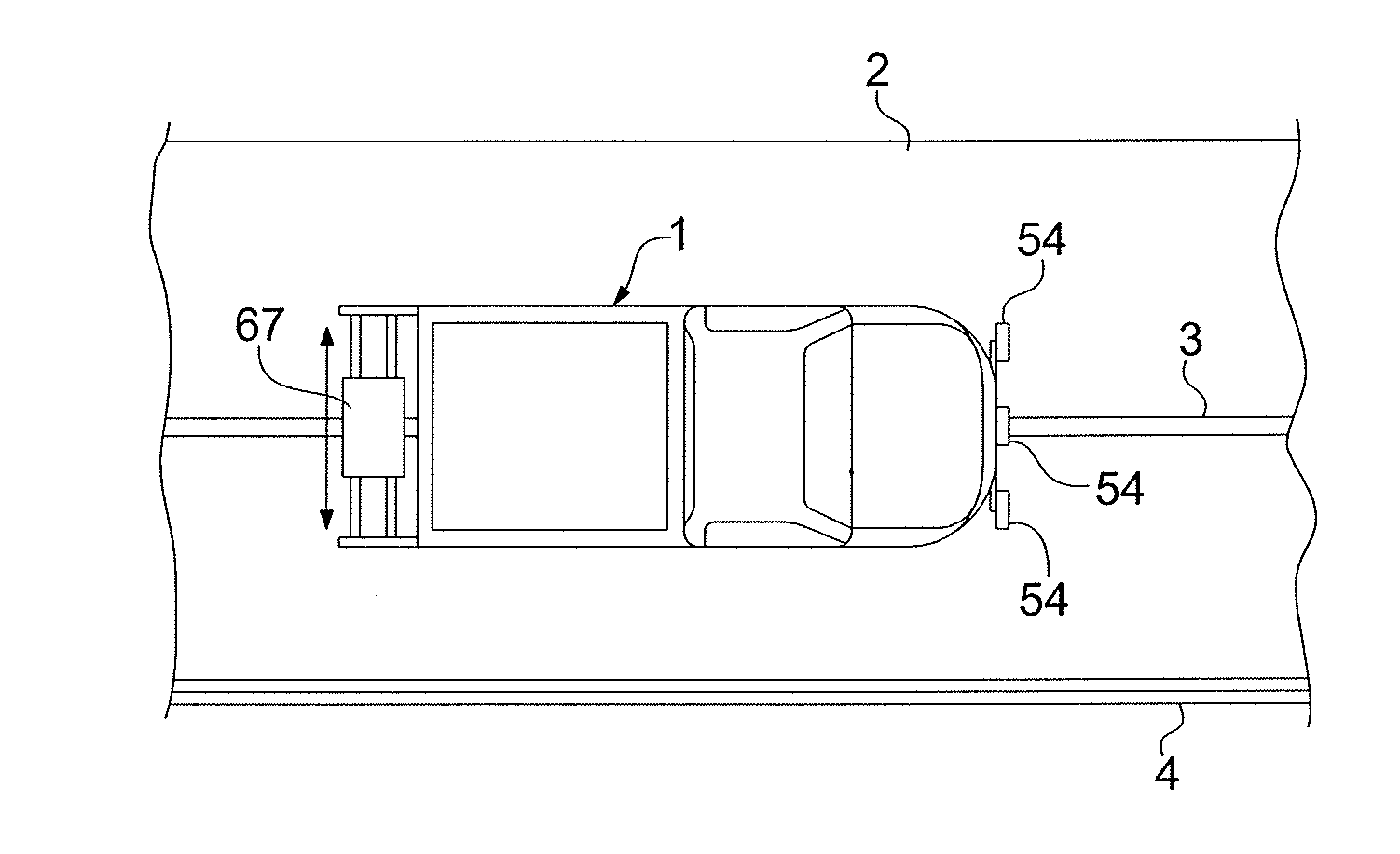
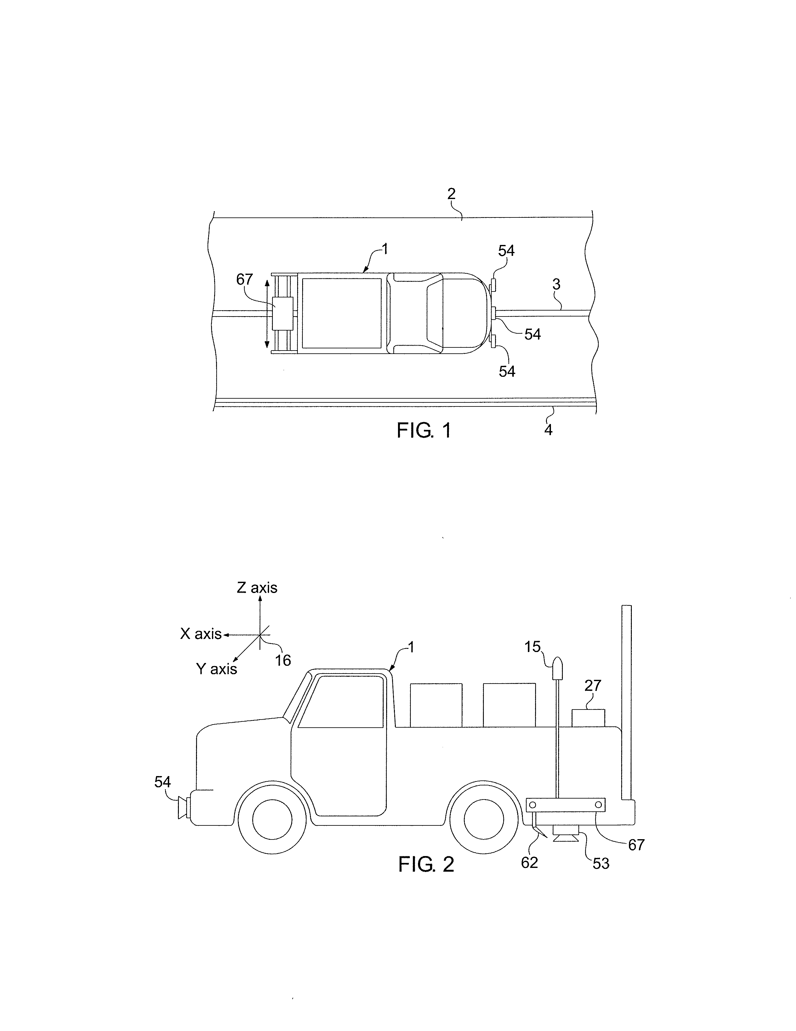
[0071]The present invention provides GPS-based systems used for painting or otherwise marking roadway traffic lane demarcation lines and vehicle mounted locating and inspection systems for determining the geographical location and condition of roadway marks. Referring now to the drawing, in which like reference numbers refer to like elements throughout the various figures that comprise the drawing, FIG. 1 shows a moving or self-propelled vehicle 1 which is located on a road or roadway 2 near a line 3 applied to the surface of the road 2. Also shown is a roadway edge boundary line 4. The term “vehicle” used in this document is given its broadest meaning, including any conveyance, motorized device, or moving piece of mechanical equipment for transporting passengers or apparatus. More specific and preferred examples of vehicles 1 are cars, vans, trucks, snow plows, construction equipment, and road marking machines. The terms “road” and “roadway” are used interchangeably in this documen...


PUM


Abstract

An apparatus for locating, inspecting, or placing marks on a roadway. The apparatus includes a GPS-based machine vision locator for sampling discrete geographical location data of a pre-existing roadway mark evident on the roadway. A computer may determine a continuous smooth geographical location function fitted to the sampled geographical location data. And a marker is responsive to the GPS-based locator and geographical location function for replicating automatically the pre-existing roadway mark onto the roadway. The apparatus is typically part of a moving vehicle. A related method is disclosed for locating, inspecting, and placing marks on a resurfaced roadway. A similar apparatus can be used to guide a vehicle having a snow plow along a snow-covered roadway, or a paving machine along an unpaved roadway surface.

Description

CROSS REFERENCE TO RELATED APPLICATIONS[0001]This application is a continuation-in-part of U.S. patent application Ser. No. 13 / 351,829, filed on Jan. 17, 2012, which is incorporated by reference into this document, in its entirety and for all purposes.TECHNICAL FIELD[0002]The present invention relates generally to GPS-based machine vision locating and inspection systems and to devices for making a visual indicia in or on top of pavement. More particularly, the present invention relates to vehicle mounted locating and inspection systems for determining the geographical location and condition of roadway marks, and GPS-based systems used for painting or otherwise “marking” roadway traffic lane demarcation lines.BACKGROUND OF THE INVENTION[0003]New or repaved roadway surfaces almost always require the application of roadway surface markings as a mechanism for visually providing motorists with lane demarcation lines for controlling and directing traffic. In the past, the process of apply...

Claims


Application Information

Patent Timeline
Patent Type & Authority Applications(United States)
IPC IPC(8): G06K9/00F16M13/02E01C23/22
CPCG01C15/02F16M13/022E01C23/22G06K9/00791E01C23/163B62D5/0463G06V20/56
Inventor DOLINAR, DOUGLAS D.HALLER, WILLIAM R.
Owner LIMNTECH
Why Eureka
Try Eureka