
Power Supply Circuit for Driving Light Emitting Diode

Inactive Publication Date: 2013-07-25
PHIHONG TECH CO LTD
View PDF6 Cites 1 Cited by
  • Summary
  • Abstract
  • Description
  • Claims
  • Application Information

AI Technical Summary

Benefits of technology

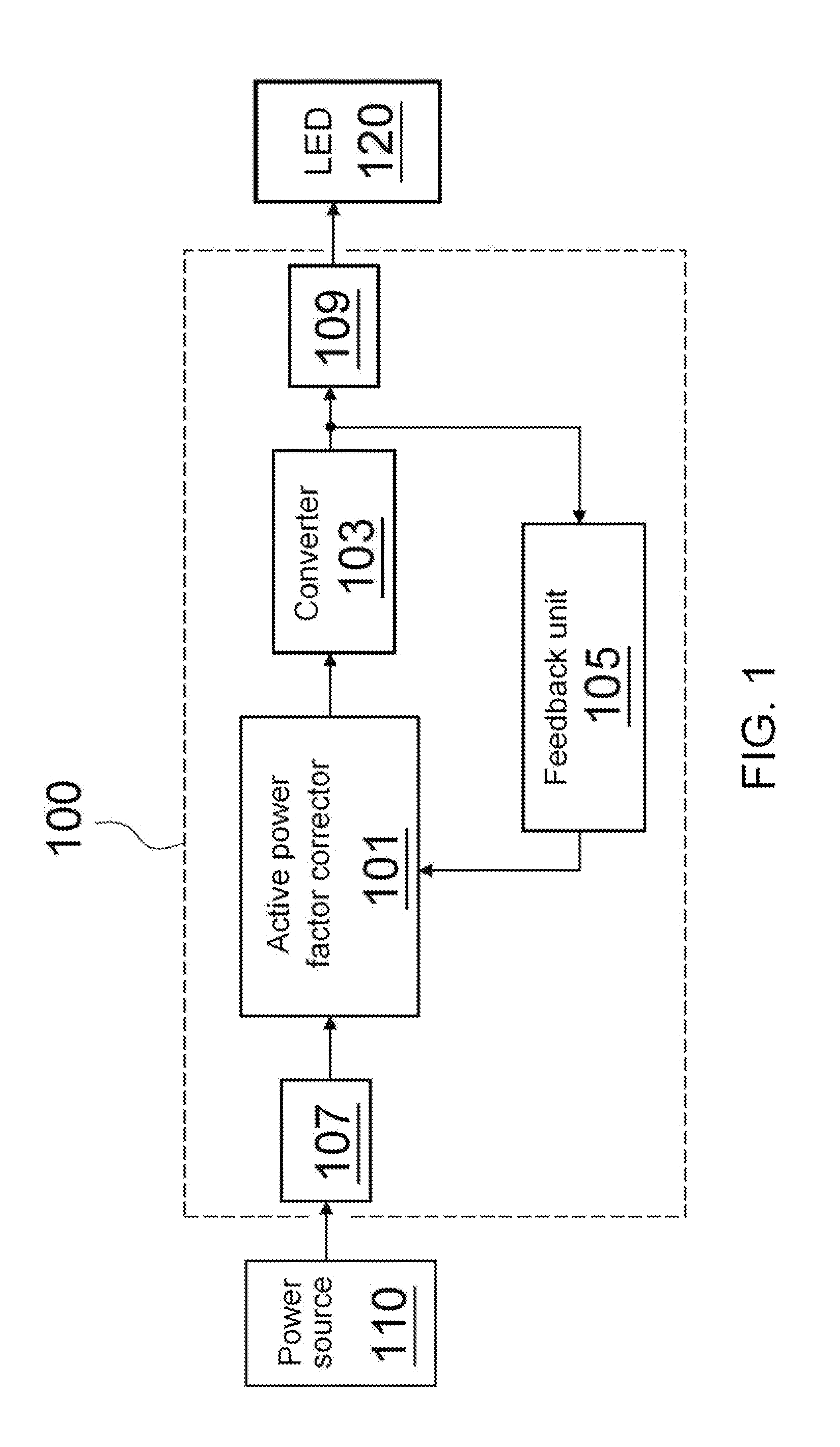
The present invention provides a power supply circuit for driving LED with high efficiency. The circuit includes an input unit, an active power factor corrector, a converter, an output unit, and a feedback unit. The feedback unit delivers the power signal back to the active power factor corrector, which modulates the power signal to stabilize the output power and drive the LED. The technical effects of the present invention are improved energy utilization and stable LED lighting.

Problems solved by technology

However, although the traditional boost-type converter has simple features and is easy for operation in the FPC, a serious harmonic wave of current is occurred due to the inputting current of inductance being a triangular wave pulse.
In contrast, if the setting value of the filter factor is smaller, the noise of the is inputting current will be more and it causes very serious electromagnetic waves interferences.
However, any changes of the outputting load will cause the circuits failure to be operated in the optimized work.
Thus, the average efficiency cannot be improved.

Method used


Image

  • Power Supply Circuit for Driving Light Emitting Diode
  • Power Supply Circuit for Driving Light Emitting Diode
  • Power Supply Circuit for Driving Light Emitting Diode

Examples


first embodiment

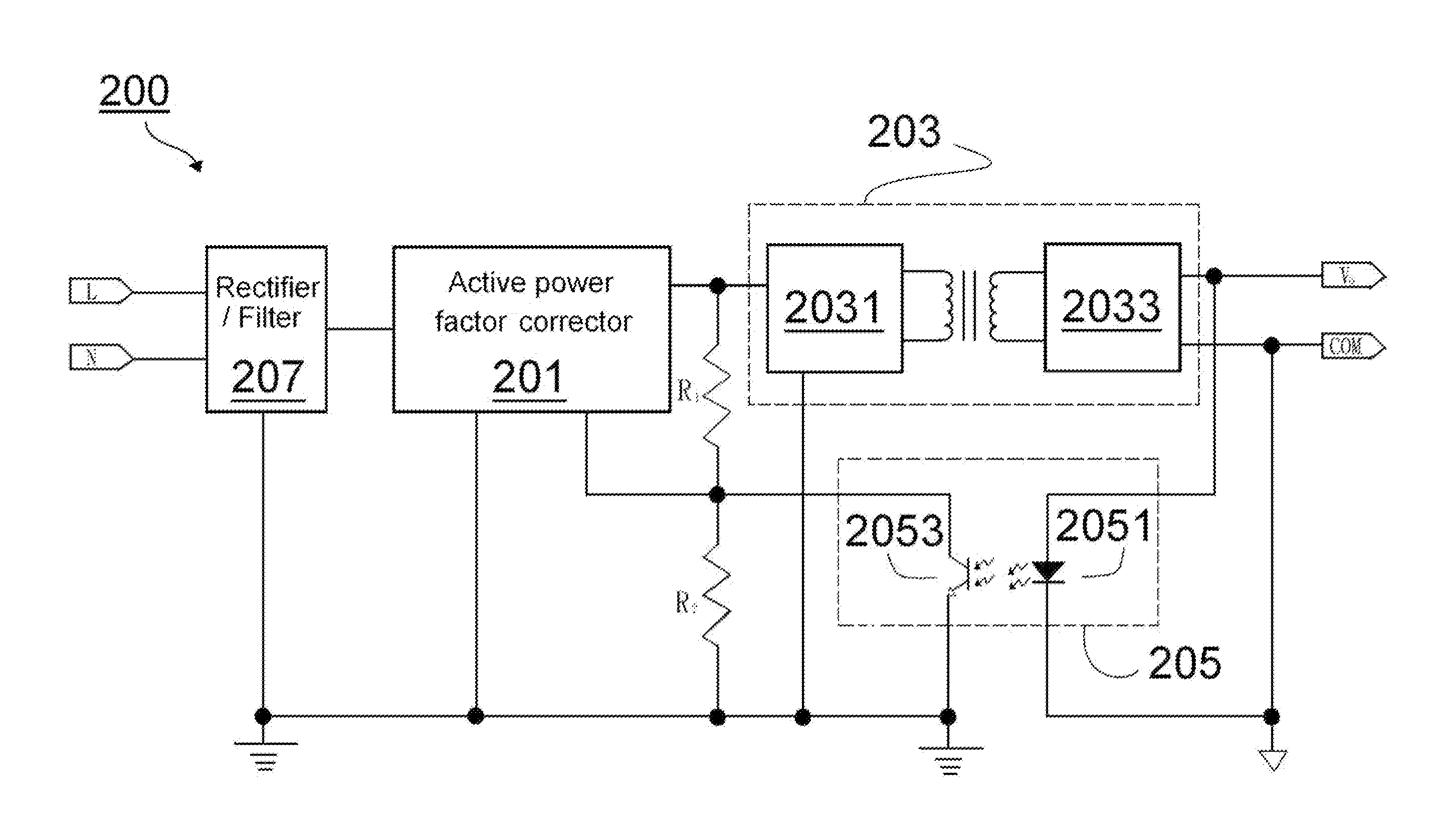
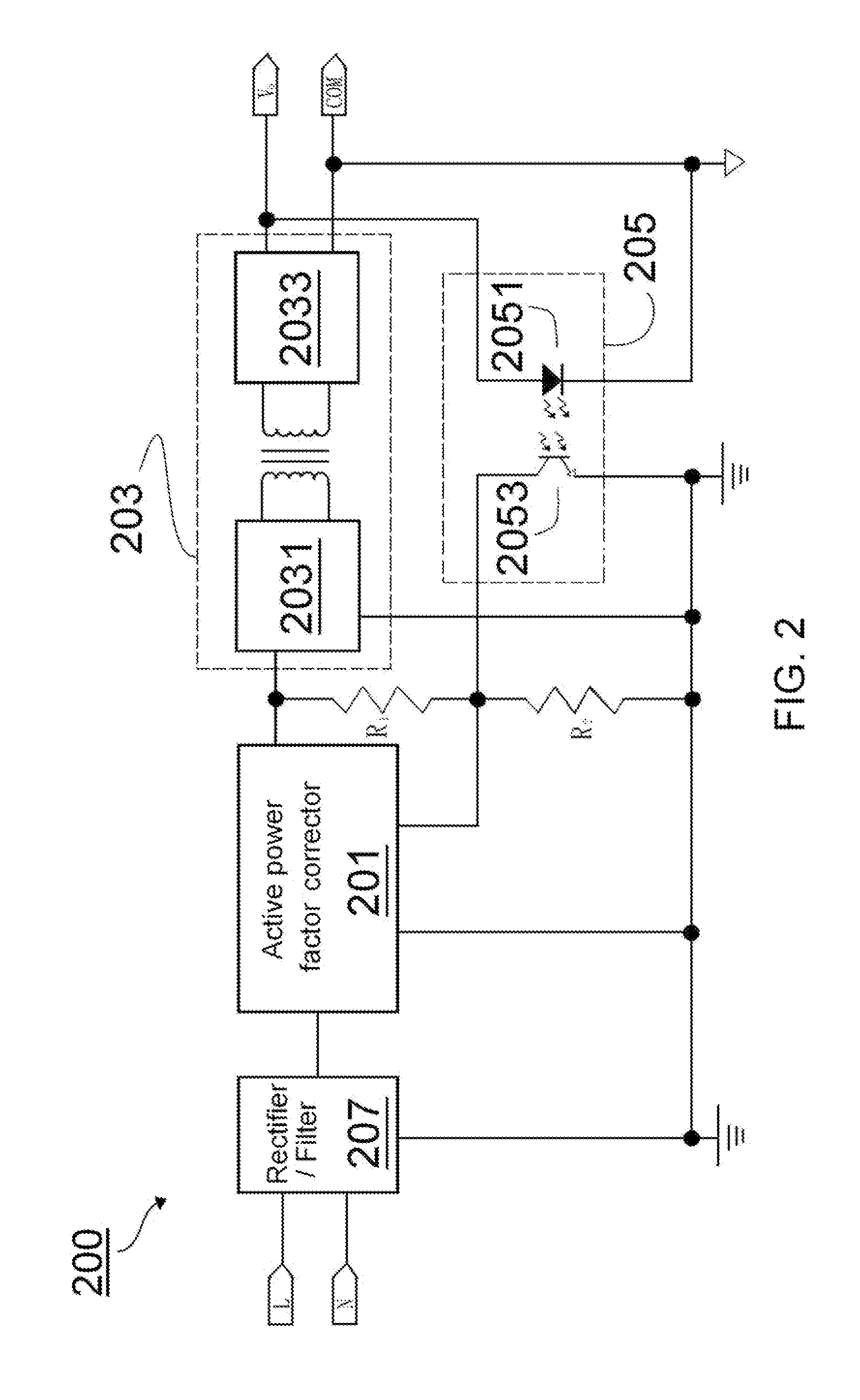
[0036]In this embodiment, referring to the schematic diagram of the equivalent circuit of the power supply circuit 200 shown in FIG. 2, the ratio of the main winding 2031 and the secondary winding 2033 of the isolated DC-DC converter 203 is 39:15, and the inductance is 350 μH. In this embodiment, a buck-type active PFC 201 is used. In full-load operations, the efficiency may reach 90.24%. However, in this case, the stability of the power supply circuit in low-load operation is not as good as the one in high-load operation.

second embodiment

[0037]In this embodiment, referring to the schematic diagram of the equivalent circuit of the power supply circuit 200 shown in FIG. 2, the ratio of the main winding 2031 and the secondary winding 2033 of the isolated DC-DC converter 203 is 152:61, and the inductance is 2200 μH. In this embodiment, a buck-type active PFC 201 is introduced. In this case, in order to stabilize the outputting voltage Vo of the power supply circuit in a very low-load operation, is the inductance and operating frequency are increased.

[0038]In this embodiment, the inductance of the isolated DC-DC converter 203 is increased in a permitting range. Therefore, the outputting voltage Vo may stably output in a very low-load operation, effectively. However, in this case, the isolated DC-DC converter 203 may reach saturation when the full-load operation is performed. Thus, the efficiency of the power supply circuit may be reduced slightly during in full-load operation.

[0039]Furthermore, in this embodiment, when t...

third embodiment

[0040]In this embodiment, referring to the schematic diagram of the equivalent circuit of the power supply circuit 200 shown in FIG. 2, the ratio of the main winding 2031 and the secondary winding 2033 of the isolated DC-DC converter 203 is defined as 80:31, and the inductance is 1000 μH. In this embodiment, a buck-type active PFC 201 is used. In this case, the winding number of the main winding 2031 and inductance is reduced to half for improving the efficiency in the full-load operation. However, in this case, the output load need to be increased to 0.15 ampere to output the stable voltage by the outputting voltage Vo. Moreover, in this embodiment, the efficiency of the power supply circuit in full-load operation may reach around 87.36%.

[0041]As the foregoing embodiments, the buck-type active PFC 201 may reduce compressive stresses effectively for improving efficiency. Furthermore, the power supply circuit 200 may get into the CCM mode in advance by is increasing the operating fre...


PUM


Abstract

The present invention relates to a power supply circuit for driving at least one light emitting diode (LED). The power supply circuit comprises: an input unit, an active power factor corrector, a converter, an output unit and a feedback unit. The input unit is utilized to receive power signal from a power source, and the output unit is utilized to receive power transferred from the converter for driving at least one LED. The feedback unit couples to a node between the converter and the output unit, and delivers the power signal, from the converter to the output unit, back to the active power factor corrector. The active power factor corrector monitors the power signal based on the power signal from the feedback unit for stabilizing the outputting power from the output unit and thereby driving the LED.

Description

BACKGROUND[0001]1. Field of Invention[0002]The present invention relates to power supply circuits, more particularly, the present invention relates to a power supply circuit for driving light emitting diodes (LEDS), and the power supply circuit could apply high-effective and stabilized outputting voltages to at least one LED.[0003]2. Description of Related Art[0004]With the increasing power requirement, a lot of scientists, engineers and manufacturers of power supply in every country all try to solve the problems about low-efficiency of power supplies.[0005]In traditional, power factor corrector (PFC) is consisted of a ferrite core and a coil. The main functions of the PFC include modulating angle of phase, reducing virtual work, improving real power, decreasing interference of harmonic waves, and improving quality of applying voltages. In addition, main effects of the PFC is to enable the phase of voltage and the phase of current to be the same, and is to enable the load to be simi...

Claims


Application Information

Patent Timeline
IPC IPC(8): H05B37/02H05B44/00
CPCH05B33/0815Y02B70/126H02M2001/007H02M1/4225Y02B70/10H05B45/382H05B45/3725H05B45/375H05B45/38H02M1/007
Inventor CHEN, CHUN CHENYEH, CHIA YINGCHEN, CHIEN LIANGYU, PO CHING
Owner PHIHONG TECH CO LTD
Learn More