
Intelligent charging solution for large-scale battery systems with scalable power output

a battery system and intelligent charging technology, applied in the field of energy storage, can solve the problems of complex set of conditions that need to be monitored, reduce the longevity (cycle life), and it is not possible to seamlessly integrate the existing standalone charging system into the end user installation

Inactive Publication Date: 2013-07-25
ELECTRIC MOTOR WERKS
View PDF3 Cites 0 Cited by
  • Summary
  • Abstract
  • Description
  • Claims
  • Application Information

AI Technical Summary

Benefits of technology

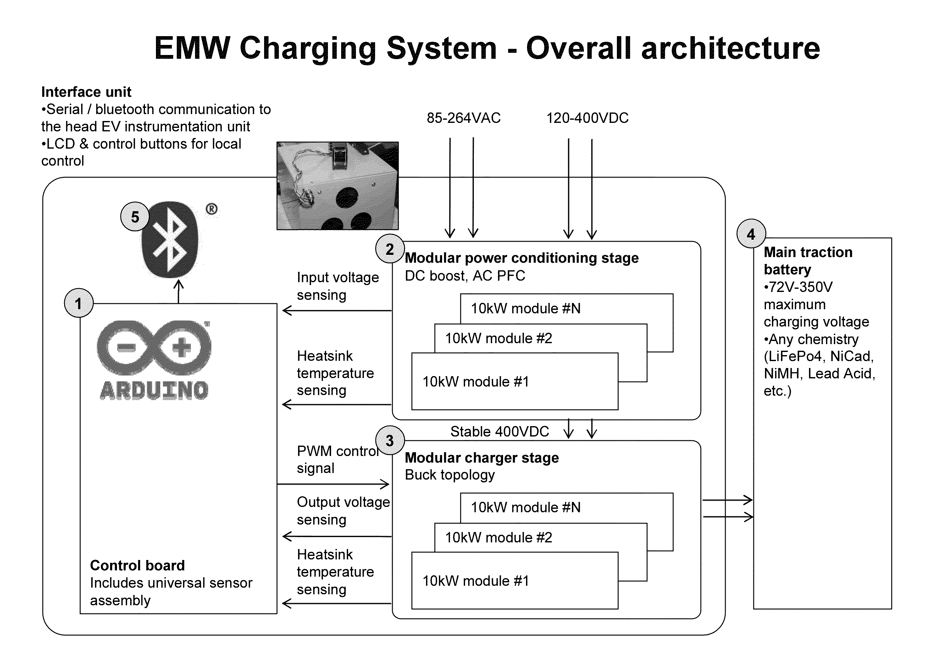
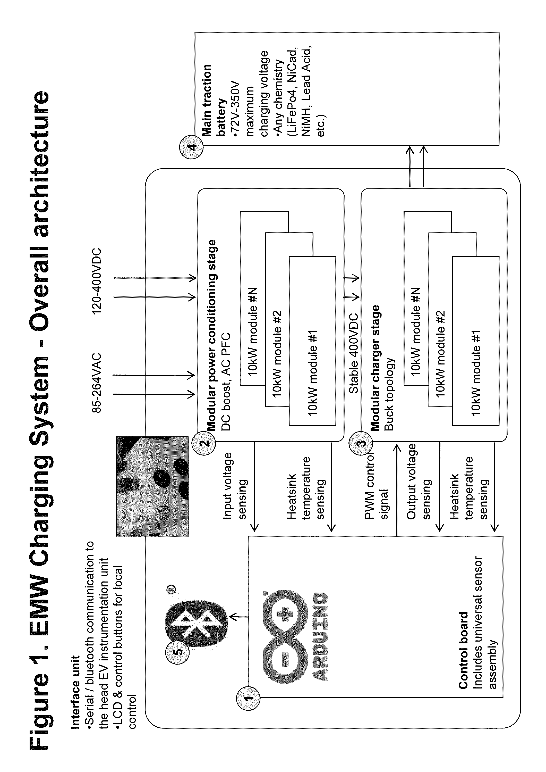
The invention offers a scalable charging system for electric vehicles, which aims to solve issues with conventional techniques for battery charging. The system includes a microprocessor-based control system with a sensor assembly, an extendable power stage delivering energy to the battery, and a remote control and monitoring hardware module executing a remote control and monitoring software. The technical effects of the invention include improved efficiency, flexibility, and scalability, which can adapt to the varying needs of electric vehicles.

Problems solved by technology

Furthermore, there are complex sets of conditions that need to be monitored to detect transition from one charging step to another.
For example, letting the battery to fully discharge and then applying full charge maximizes the energy output of the battery but at the same time dramatically reduces its longevity (cycle life).
Furthermore, it is not possible to seamlessly integrate the existing standalone charging systems into the end user installation (emergency home energy storage, electric vehicle battery, etc) without modifications from the manufacturer.
Additionally, the available systems have fixed maximum power settings, limiting user's ability to scale up the charging power as needed.
Today, this solution is not possible to implement without significant redundancy, weight, and cost (as two completely separate systems would be required).

Method used


Image

  • Intelligent charging solution for large-scale battery systems with scalable power output
  • Intelligent charging solution for large-scale battery systems with scalable power output
  • Intelligent charging solution for large-scale battery systems with scalable power output

Examples


Embodiment Construction

[0019]In the following detailed description, reference will be made to the accompanying drawing(s), in which identical functional elements are designated with like numerals. The aforementioned accompanying drawings show by way of illustration, and not by way of limitation, specific embodiments and implementations consistent with principles of the present invention. These implementations are described in sufficient detail to enable those skilled in the art to practice the invention and it is to be understood that other implementations may be utilized and that structural changes and / or substitutions of various elements may be made without departing from the scope and spirit of present invention. The following detailed description is, therefore, not to be construed in a limited sense.

[0020]The inventive methodology is directed to methods and systems that substantially obviate one or more of the above and other problems associated with conventional techniques for charging large-scale (>...


PUM


Abstract

A scalable battery charging system and a probe system for charging large-scale battery systems. System incorporates (1) a control board with an extensible universal sensor assembly to monitor all relevant input and output parameters, (2) extensible power stage that can be scaled to the arbitrary levels of power by stacking power modules, and (3) remote control and monitoring hardware and software. This inventive system allows for more automated, lower cost, and higher lifetime usage of the large-scale battery systems. It will also allow for better user experience through better control over the process and automation of the traditionally manual steps.

Description

CROSS-REFERENCE TO RELATED APPLICATIONS [0001]The present patent application relies on and claims the benefit or priority of U.S. provisional patent application No. 61 / 557,423 filed Nov. 9, 2011, the entire disclosure of which is incorporated by reference herein.BACKGROUND OF THE INVENTION [0002]1. Field of the Invention[0003]The present invention relates generally to the field of energy storage and in particular to electric vehicle battery charging, and the electronic systems used in this process.[0004]2. Description of the Related Art[0005]Large energy storage systems in general and electric vehicles battery systems in particular incorporate arrays of electrochemical energy storage devices (batteries) electrically connected in a combination of series and parallel arrangements to arrive at the necessary system voltage and current capabilities. The batteries are complex layered structures consisting of several functional components: an anode, a cathode, and electrolyte. The electroc...

Claims


Application Information

Patent Timeline
IPC IPC(8): H02J7/00
CPCH02J7/007Y02T90/168Y04S30/12Y02E60/721H02J3/32H02J7/022Y04S10/126H02J3/1892H02J2310/48H02J7/02H02J2207/20Y02T90/167H02J3/322Y02E60/00
Inventor MIFTAKHOV, VALERY
Owner ELECTRIC MOTOR WERKS
Learn More