Electronic device

Inactive Publication Date: 2013-07-25
ALPS ALPINE CO LTD
View PDF3 Cites 6 Cited by
  • Summary
  • Abstract
  • Description
  • Claims
  • Application Information

AI Technical Summary

Benefits of technology

[0014]In the above configuration, for easy designing and processing, it is preferable that the mounting board has a simple shape such that the mounting board has a substantially square shape when viewed in plan, a power-feeding leg piece and a first short-circuiting leg piece are formed in a portion that is on one of substantially parallel sides of the mounting board and that is bent toward the circuit board and a second short-circuiting leg piece is formed in a portion that is on the other side of the mounting board and that is bent toward the circuit board.
[0015]The present invention has been made by focusing on an electrically conductive mounting board being often used in an electronic component that includes an operation portion. In the invention, the mounting board is caused to operate as an antenna by forming a power-feeding leg piece at a predetermined position of the mounting

Problems solved by technology

These operations are complicated and thus increase the cost of installation.
However, the antenna needs to be selectively positioned considering the positional

Method used


Image

  • Electronic device
  • Electronic device
  • Electronic device

Examples


Embodiment Construction

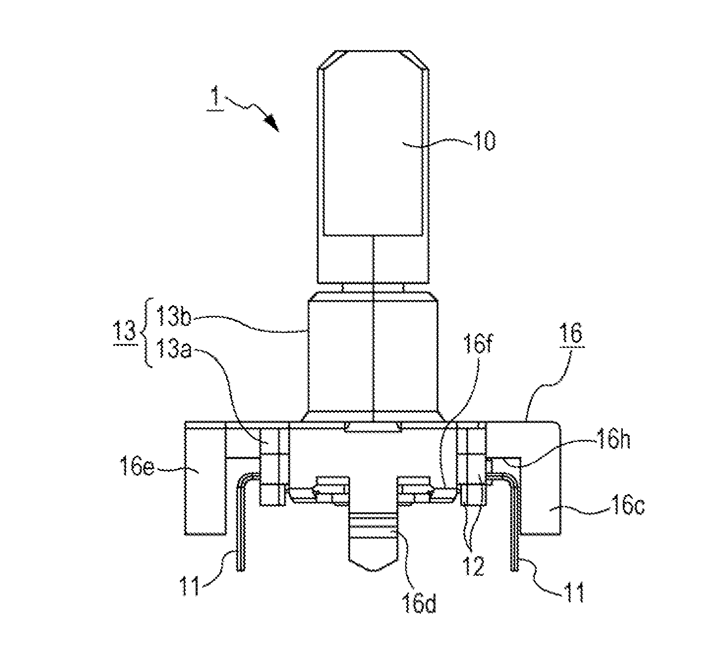
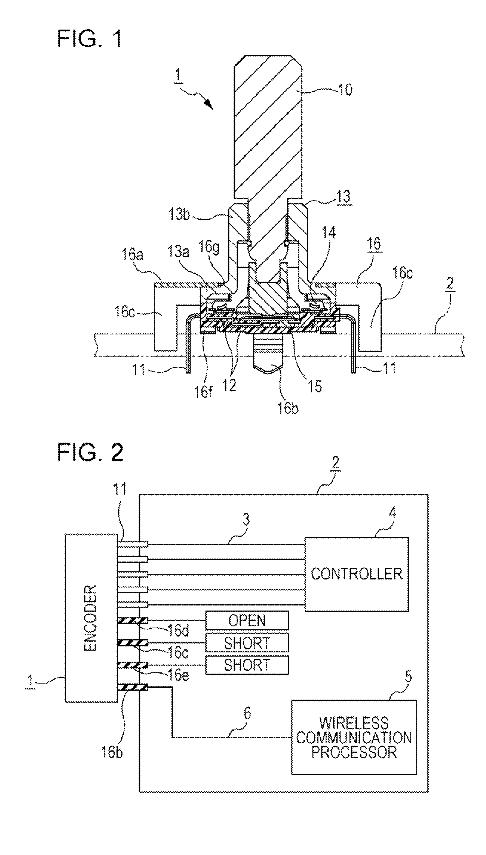
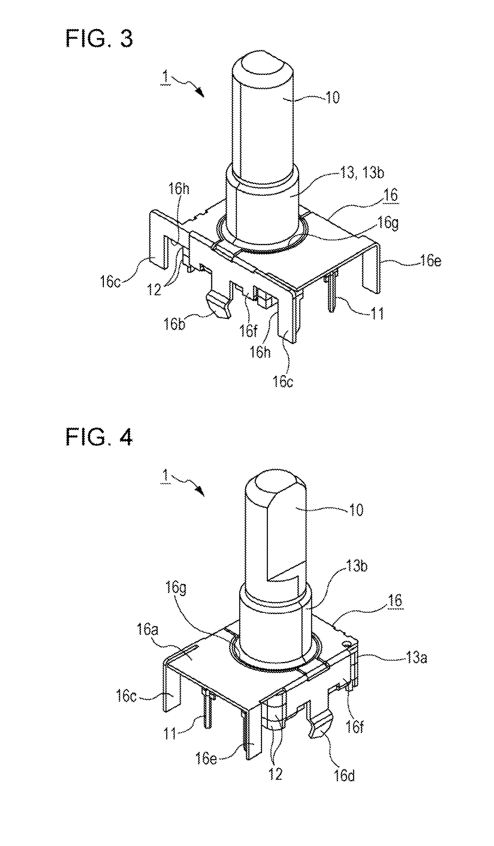
[0024]Referring to the drawings, electronic devices according to embodiments of the present invention will be described below. Firstly, an electronic device according to a first embodiment is described with reference to FIGS. 1 to 5. The electronic device according to the first embodiment is an in-car electronic device, such as a car navigation system, in which multiple operation portions are disposed at such positions of a car as to be operable by users in the car. One of the multiple operation portions is an operation body 10 of the encoder 1 illustrated in FIG. 1 and FIGS. 3 to 5.

[0025]As illustrated in FIG. 1, the encoder 1 is mounted on a circuit board 2. As illustrated in FIG. 2, multiple external connection terminals 11 of the encoder 1 are electrically connected to a controller 4 via corresponding wiring patterns 3 on the circuit board 2. The controller 4 is disposed on the circuit board 2. When a user manually operates the operation body 10 of the encoder 1, the controller ...


PUM


Abstract

An electronic component (encoder) including an operation body is mounted on a circuit board. The electronic component causes a controller to perform processing in accordance with an operation input by the operation body. The mounting board includes a power-feeding leg piece connected to a wireless communication processor so that high frequency communication is allowed, a first short-circuiting leg piece that is adjacent to the power-feeding leg piece via a cut-out portion, and a second short-circuiting leg piece separated from the power-feeding leg piece. The short-circuiting leg pieces are connected to grounded portions. The impedance is adjusted by appropriately selecting the width or the depth of the cut-out portion. The resonance frequency is adjusted by appropriately selecting the size or the position of the short-circuiting leg piece. Thus, the mounting board operates as an inverted-F antenna in which the power-feeding leg piece functions as a power feeding portion.

Description

CLAIM OF PRIORITY[0001]This application is a Continuation of International Application No. PCT / JP2011 / 068273 filed on Aug. 10, 2011, which claims benefit of Japanese Patent Application No. 2010-212223 filed on Sep. 22, 2010. The entire contents of each application noted above are hereby incorporated by reference.BACKGROUND OF THE INVENTION[0002]1. Field of the Invention[0003]The present invention relates to electronic devices that can perform an input operation using an operation portion and that can perform wireless communication. The present invention particularly relates to an electronic device having a wireless communication function suitable as, for example, an in-car electronic device.[0004]2. Description of the Related Art[0005]In recent years, some in-car electronic devices such as car navigation systems have been equipped with an antenna and a transmission-and-reception circuit (wireless communication processor) so as to have a wireless communication function with which the...

Claims


Application Information

Patent Timeline
IPC IPC(8): H04B1/38H01Q1/22H01Q1/32H01Q1/44
CPCH01Q1/44H04B1/3822H01Q9/0421
Inventor LI, XISUZUKI, TOMOTAKASATO, MAKOTOOTAKE, HIDEHARU
Owner ALPS ALPINE CO LTD
Why Eureka
Try Eureka