Refining system and method for refining a feed gas stream

a technology of feed gas and refining system, which is applied in the direction of gaseous fuels, lighting and heating apparatus, separation processes, etc., can solve the problems of large co2 volume, large loss of heavier hydrocarbons, and reduced efficiency

Active Publication Date: 2013-08-01
TWISTER BV
View PDF2 Cites 19 Cited by
  • Summary
  • Abstract
  • Description
  • Claims
  • Application Information

AI Technical Summary

Benefits of technology

[0007]It is an objective of the present invention to overcome or mitigate one or more of these disadvantages—associated with the state of the art technology—by offering a refining system and method for refining a feed gas stream in accordance with the preamble of claims 1 and 32.

Problems solved by technology

However, one of the disadvantages of such an absorption process is that it becomes less efficient when the CO2 concentration in the feed stream exceeds 30 mole %.
With more stringent CO2 emission regulations to come, this large CO2 volume exhibits a big problem for further handling (i.e., sequestration / further processing).
Another disadvantage is the relatively large amount of heavier hydrocarbons which are lost via the column bottom stream.
Therefore, the main disadvantage of these sophisticated cryogenic processes is the excessive cooling duties required to operate the column at these low temperatures.
The main disadvantage of membranes is the relatively high slip stream of light hydrocarbons which remains in the CO2 enriched, low pressure permeate stream.
As a consequence the total required membrane surface to treat large amounts of CO2 in natural gas is enormous and therefore practically impossible for large gas fields.
A further disadvantage of membranes is their sensitivity to heavier hydrocarbons, water and fine solid matter, which will significantly reduce the flux and selectivity (i.e., performance) of the membrane over time.

Method used


Image

  • Refining system and method for refining a feed gas stream
  • Refining system and method for refining a feed gas stream
  • Refining system and method for refining a feed gas stream

Examples


Embodiment Construction

[0030]In practice, gas field conditions can vary with respect to the CO2 concentration in the feed gas stream, the available feed pressure and required export pressure, the required export concentration of CO2 in the export gas stream after refining (i.e. so-called “sales gas”) and the required hydrocarbon recovery from the produced CO2 liquid. Each gas field development will therefore require a tailored process design. However, the generic process (block) scheme as presented in this invention will be similar for all field conditions.

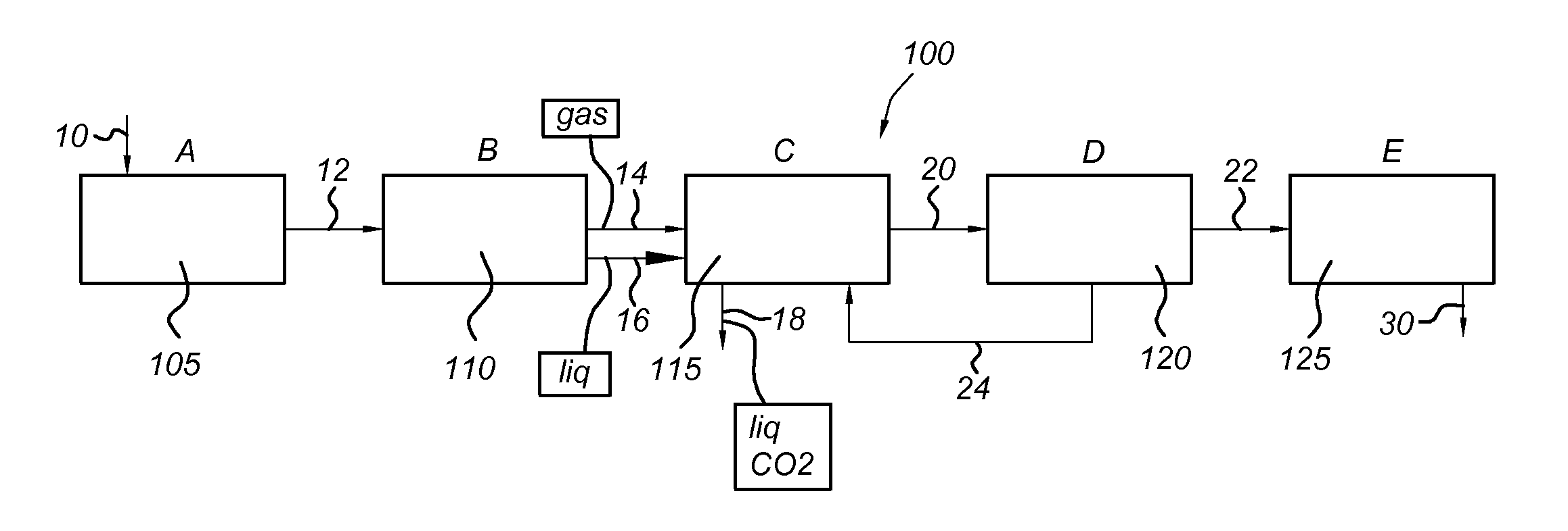
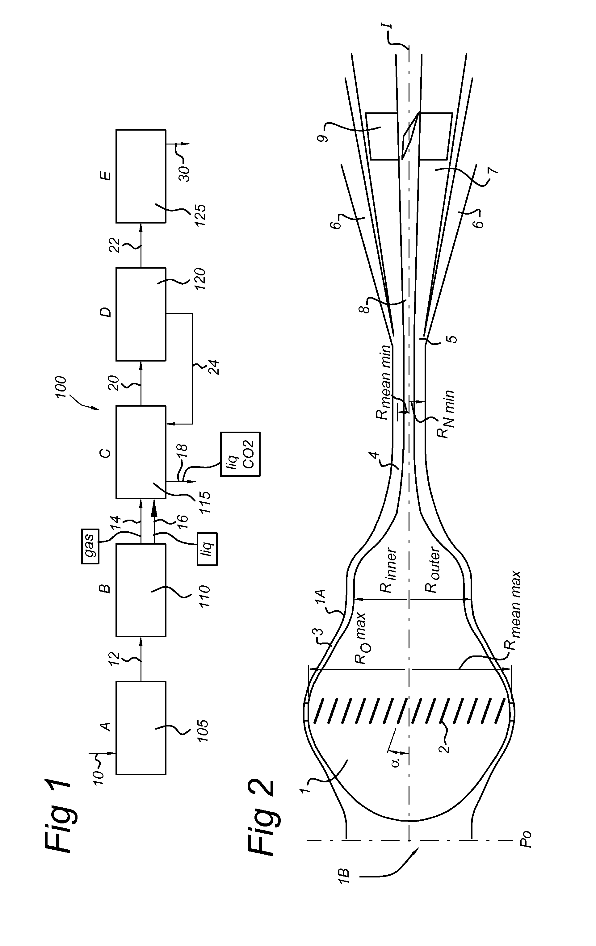
[0031]FIG. 1 shows a processing scheme 100 according to the present invention.

[0032]The processing scheme comprises a number of processing stages or blocks 105, 110, 115, 120, 125 that process / refine a feed gas stream 10 into an export gas stream 30.

[0033]A refining system according to the processing scheme 100 comprises a first processing block 105 for dehydrating the gas stream, a second processing block 110 for pre-cooling the gas stream, a third pro...


PUM

PropertyMeasurementUnit
water dew pointaaaaaaaaaa
pressureaaaaaaaaaa

Abstract

A refining system for refining a feed gas (10) includes a first and a second component, the first component having a lower dew point temperature than the second component; the refining system including:—an input section (105) for input of the feed gas including a dehydration unit for dehydrating the feed gas, capable of obtaining a water dew point between −45 and −65° C.;—a pre-cooling section (110) coupled to the input section for receiving the dehydrated feed gas;—a fractionation section (115) coupled to the pre-cooling section for receiving the pre-cooled stream;—an expansion cooling and separation section (120) coupled to the fractionation section for receiving the fractionated gas, including a cyclonic separator device (240); the expansion cooling and separation section having an reflux conduit coupled to the fractionation section for reflux (24) of liquid enriched with the second component to the fractionation section.

Description

FIELD OF THE INVENTION[0001]The present invention relates to a refining system for refining a feed gas stream comprising a first component and at least a second component. Also, the present invention relates to a method for refining a gas stream comprising a first component and at least a second component.BACKGROUND[0002]Depending on gas field conditions natural gas streams of methane and other volatile hydrocarbons as first component are mixed with varying amounts of a second component such as CO2 (carbon dioxide).[0003]Traditionally, CO2 (carbon dioxide) is removed from natural gas streams by selective dissolving the CO2 (solute) in a solvent. The solute and the solvent are contacted in a counter-current column (packed / trays). However, one of the disadvantages of such an absorption process is that it becomes less efficient when the CO2 concentration in the feed stream exceeds 30 mole %.[0004]Moreover, the CO2 laden solvent is regenerated at low pressure (close to atmospheric press...

Claims


Application Information

Patent Timeline
Patent Type & Authority Applications(United States)
IPC IPC(8): F25J1/00
CPCB01D53/002F25J1/00B01D53/28B01D2252/10B01D2256/22B01D2256/24B01D2256/245B01D2257/304B01D2257/504C10L3/104C10L3/106F25J3/0209F25J3/0233F25J3/0266F25J3/061F25J3/0635F25J3/067F25J2200/02F25J2200/74F25J2205/04F25J2205/20F25J2210/04F25J2215/04F25J2220/68F25J2230/08F25J2230/60F25J2240/02F25J2240/40F25J2245/02F25J2260/80F25J2270/02F25J2270/06Y02C10/12B01D53/263Y02C20/40F25J2205/10F25J2205/40F25J2215/80F25J2220/60
Inventor BETTING, MARCOVAN BAKEL, ROBERT PETRUSTJEENK WILLINK, CORNELIS ANTONIESHETTAR, SANTOSH
Owner TWISTER BV
Why Eureka
Try Eureka