Method and system for calibrating an ultrasonic wedge and a probe

Active Publication Date: 2013-08-01
GENERAL ELECTRIC CO
View PDF2 Cites 5 Cited by
  • Summary
  • Abstract
  • Description
  • Claims
  • Application Information

AI Technical Summary

Benefits of technology

[0009]An advantage that may be realized in the practice of some disclosed embodiments of the method for calibration is to simplify the calibration method and avoid the

Problems solved by technology

For example, if the phased array transducer has elements that are not operating properly or the ultrasonic wedge experienced wear that changes its geometry, the calibration,

Method used


Image

  • Method and system for calibrating an ultrasonic wedge and a probe
  • Method and system for calibrating an ultrasonic wedge and a probe
  • Method and system for calibrating an ultrasonic wedge and a probe

Examples


Embodiment Construction

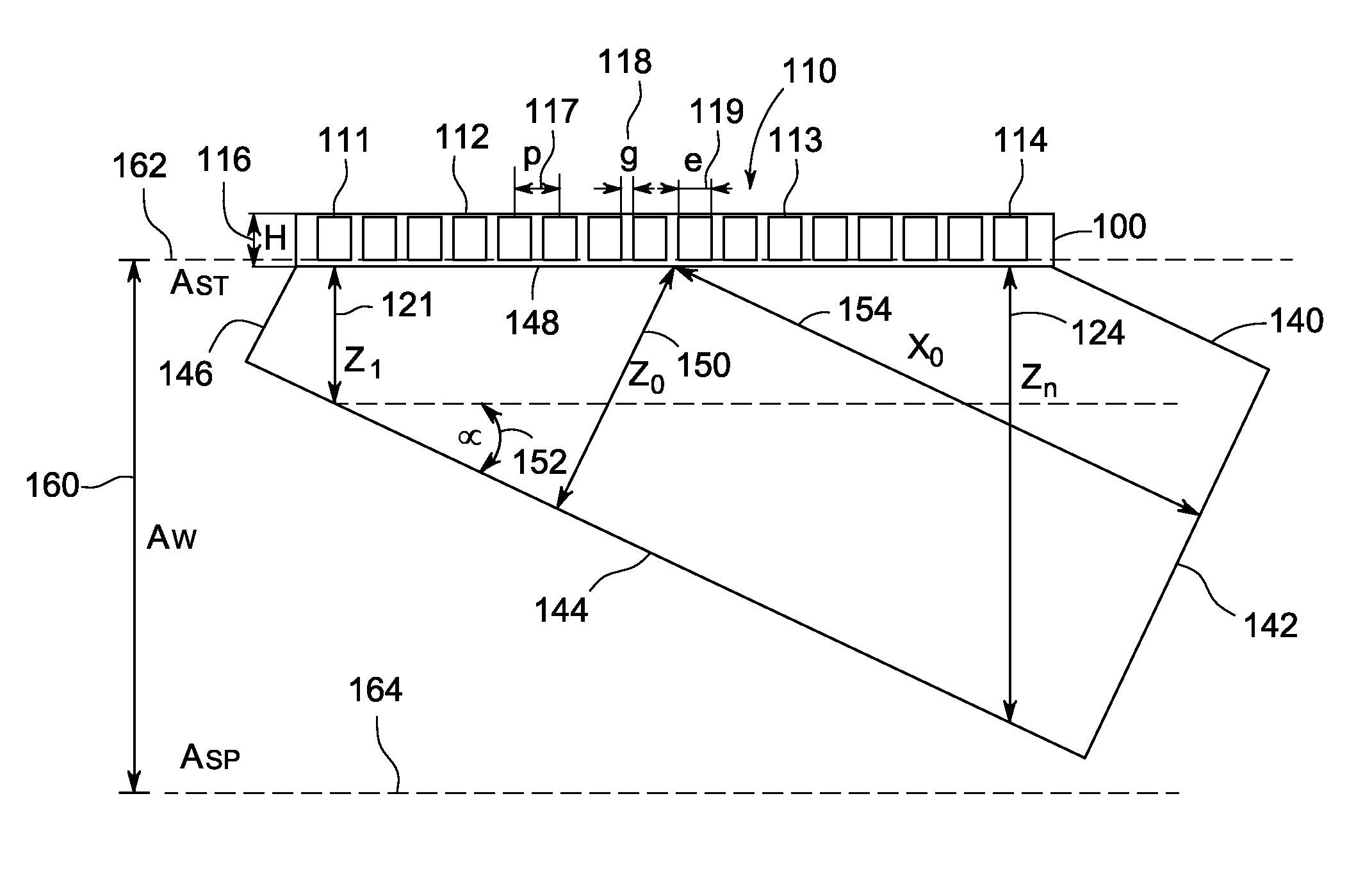
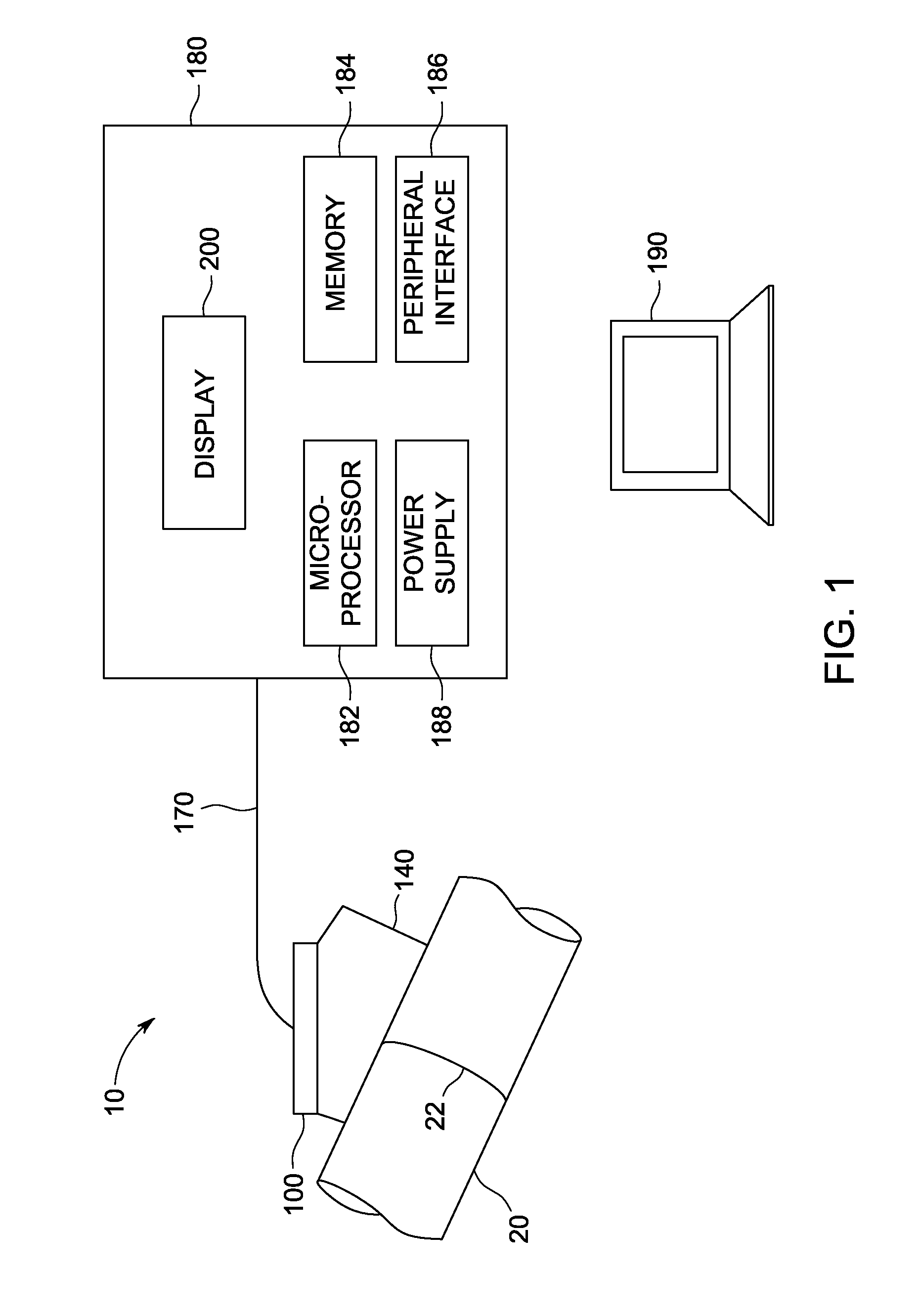
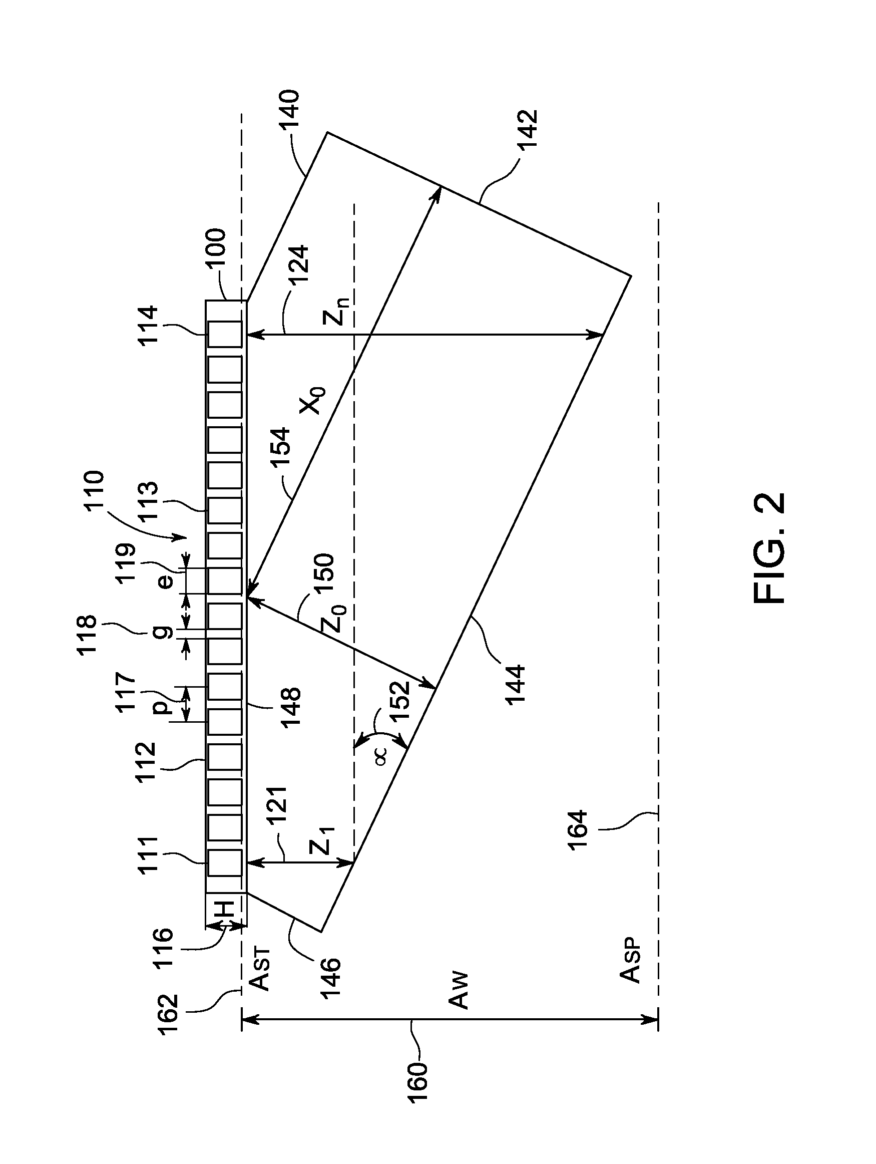
[0019]FIG. 1 is a block diagram of an exemplary ultrasonic testing system 10. In one embodiment, the ultrasonic testing system 10 is used to inspect a test object (e.g., the weld 22 of a conduit 20). The ultrasonic testing system 10 can comprise a probe 100, that can include an array of ultrasonic transducer elements (i.e., in a phased array transducer 110) (as shown in FIG. 2). The probe 100 can be mounted on an ultrasonic wedge 140 that can be attached to the test object. The ultrasonic wedge 140 can be made from any material that has an acoustic velocity different from that of the test object. For example, some ultrasonic wedges are made from plastics such as plexi-glass or a polystyrene material through which sound travels at a known velocity. The amplitude and firing sequence of the individual transducer elements of the phased array transducer 110 can be controlled in order to adjust the angle and penetration strength of the ultrasonic signal that is sent into the test object.

[...


PUM


Abstract

A method and system for calibrating an ultrasonic wedge and a probe are disclosed. The calibration method includes the steps of automatically determining the ultrasonic signal acquisition width and the first ultrasonic signal gate based on the theoretical parameters of the ultrasonic wedge and the probe. The calibration method can also include the steps of automatically determining the operating status of transducer elements in a phased array transducer and then determining the actual parameters of the ultrasonic wedge based on the live transducer elements.

Description

BACKGROUND OF THE INVENTION[0001]The subject matter disclosed herein relates to ultrasonic testing, and more particularly, a method and system for calibrating an ultrasonic wedge and a probe.[0002]Nondestructive testing devices can be used to inspect test objects to identify and analyze anomalies in the objects. Nondestructive testing allows an inspection technician to maneuver a probe at or near the surface of the test object in order to perform testing of both the object surface and underlying structure. Nondestructive testing can be particularly useful in some industries, e.g., aerospace, power generation, and oil and gas transport or refining, where inspection of test objects must take place without removal of the object from surrounding structures, and where hidden anomalies can be located that would otherwise not be identifiable through visual inspection.[0003]One example of nondestructive testing is ultrasonic testing. When conducting ultrasonic testing, an ultrasonic pulse c...

Claims


Application Information

Patent Timeline
IPC IPC(8): G01N29/30
CPCG01N29/0645G01N29/30G01N29/262G01N29/2487
Inventor S, ANANDAMURUGANJOBST, MATTHIASPOIRIER, JEROME
Owner GENERAL ELECTRIC CO
Why Eureka
Try Eureka