Optical layered body, polarizer and image display device

a technology of optical layered body and polarizer, which is applied in the direction of polarising elements, instruments, synthetic resin layered products, etc., can solve the problems of poor heat and humidity resistance of cellulose ester film, affecting the display quality of image display devices, and reducing the performance of polarizers such as polarization and hue control, so as to achieve excellent adhesion between polyester base and hard coat layer

Active Publication Date: 2013-08-01
DAI NIPPON PRINTING CO LTD
View PDF7 Cites 41 Cited by
  • Summary
  • Abstract
  • Description
  • Claims
  • Application Information

AI Technical Summary

Benefits of technology

[0204]The optical layered body of the present invention has the above configuration so that the adhesiveness between the polyester base and the hard coat layer is excellent, and occurrence of rainbow interference pattern and interference fringes in the images displayed on the liquid crystal display device is highly suppressed. Accordingly, the optical layered body of the present invention is suitably used for displays such as cathode ray tube displays (CRT), liquid crystal displays (LCD), plasma displays (PDP), electro luminescence displays (ELD), electric papers, and tablet PCs, especially for high-definition displays.

Problems solved by technology

Cellulose esters hardly influence the display quality of image display devices because of their low retardation values and have appropriate permeability.
Cellulose ester films, however, have poor heat and humidity resistance.
Use of a hard coating film as a polarizer protective film in a high-temperature and high-humidity environment problematically lowers performances of a polarizer such as polarization and hue control.

Method used


Image

  • Optical layered body, polarizer and image display device
  • Optical layered body, polarizer and image display device
  • Optical layered body, polarizer and image display device

Examples


example 1

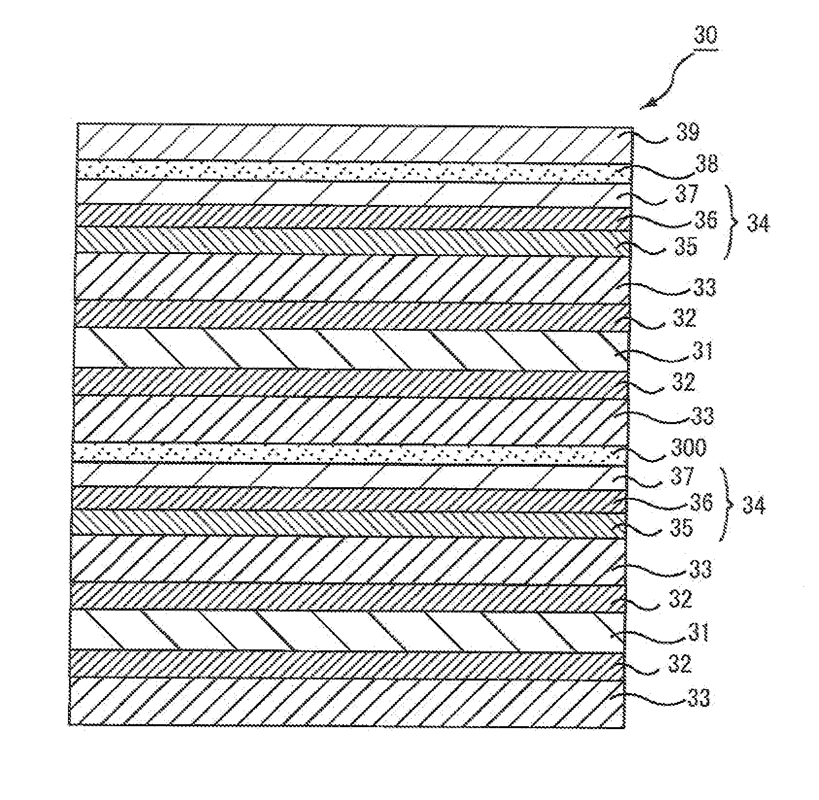
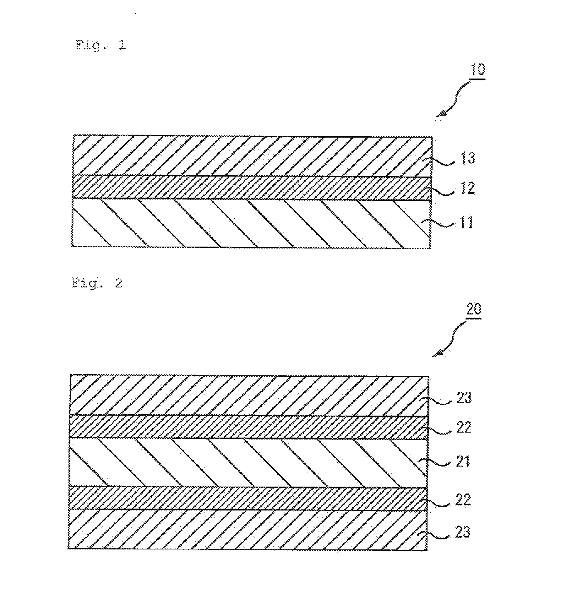
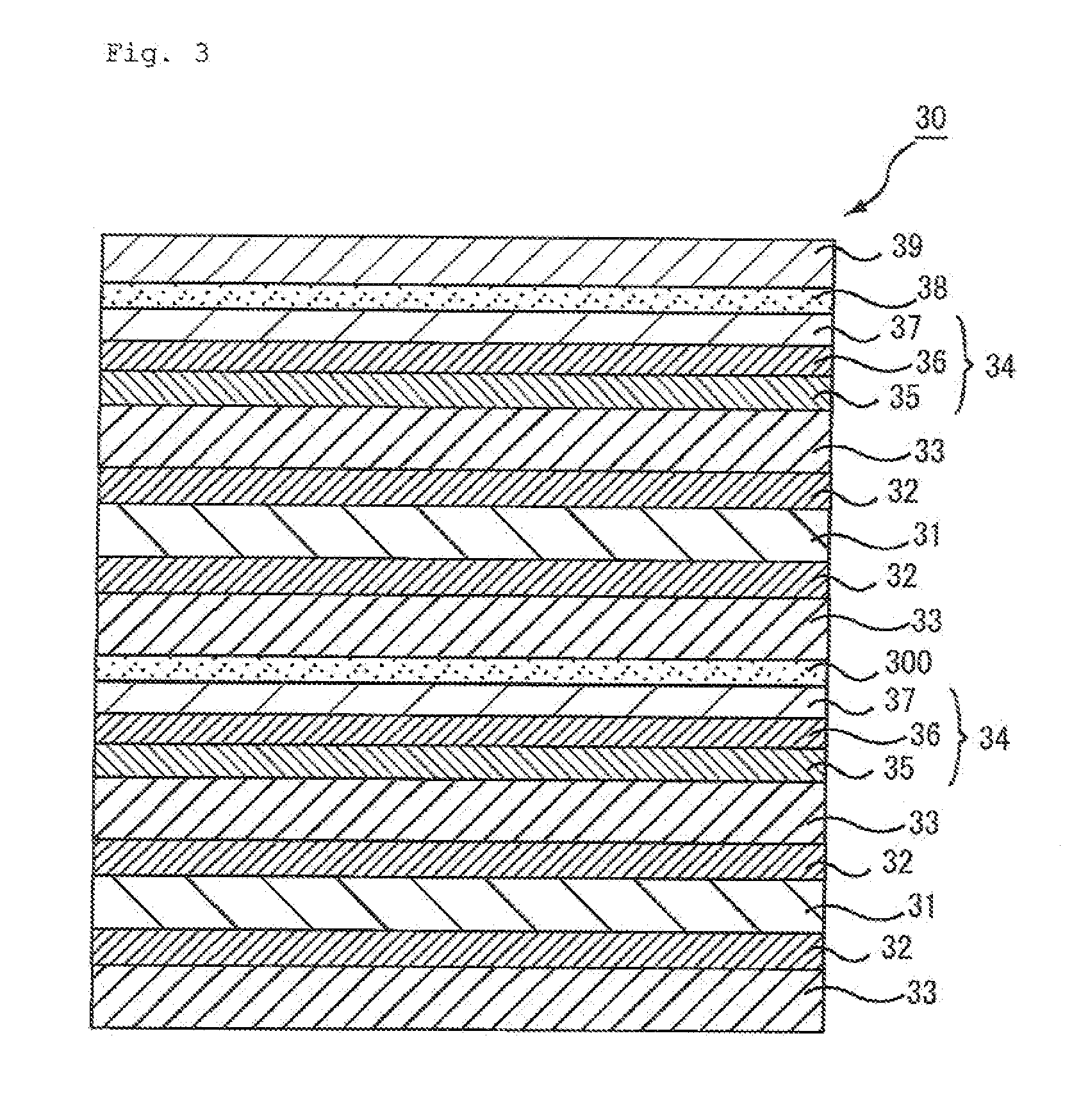
[0227]Melting polyethylene terephthalate was molten at 290° C. and extruded into a sheet-shaped film through a film-forming dye. The film was made in contact with a rotational quenching drum chilled with water for cooling purposes, so that an unstretched film was produced.

[0228]The unstretched film was preheated at 120° C. for a minute, and then stretched by 4.5 times using a biaxial film stretching tester (TOYO SEIKI SEISAKU-SHO LTD.). Then, the composition 1 for a primer layer was uniformly applied to both faces of the stretched film with a roll coater.

[0229]Next, the resulting film was dried at 95° C. and stretched by 1.5 times in a direction at 90 degrees to the stretching direction. As a result, a polyester base (retardation of 10000 nm, film thickness of 100 μm, nx of 1.70, ny of 1.60, Δn of 0.10) was obtained. The primer layer had a refractive index of 1.65 and a film thickness of 100 nm.

[0230]To the formed primer layer, the composition 1 for a hard coat layer was applied wit...

example 2

[0233]An optical layered body was produced in the same manner as in Example 1 except that the composition 3 for a hard coat layer was used instead of the composition 1 for a hard coat layer. The hard coat layer had a refractive index of 1.61.

example 3

[0234]Melting polyethylene terephthalate was molten at 290° C. and extruded into a sheet-shaped film through a film-forming dye. The film was made in contact with a rotational quenching drum chilled with water for cooling purposes, so that an unstretched film was produced.

[0235]The unstretched film was preheated at 120° C. for a minute, and then stretched by 5.2 times using a biaxial film stretching tester (TOYO SEIKI SEISAKU-SHO LTD.). Then, the composition 2 for a primer layer was uniformly applied to both faces of the stretched film with a roll coater.

[0236]Next, the resulting film was dried at 95° C. and stretched by 1.2 times in a direction at 90 degrees to the stretching direction. As a result, a polyester base (retardation of 9000 nm, film thickness of 60 μm, nx of 1.73, ny of 1.58, Δn of 0.15) was obtained. The primer layer had a refractive index of 1.57 and a film thickness of 20 nm.

[0237]To the formed primer layer, the composition 1 for a hard coat layer was applied with a...


PUM

PropertyMeasurementUnit
refractive indexaaaaaaaaaa
thicknessaaaaaaaaaa
refractive indexaaaaaaaaaa

Abstract

Provided is an optical layered body that includes a polyester base, a primer layer formed thereon, and a hard coat layer formed on the primer. The polyester has a retardation of not less than 8000 nm, and a difference (nx−ny) of 0.07 to 0.20 between a refractive index (nx) in a slow axis direction that is a high refractive index direction and a refractive index (ny) of a fast axis direction that is orthogonal to the slow axis direction, a refractive index (np) of the primer, the refractive index (nx) in the slow axis direction of the polyester, and the refractive index (ny) in the fast axis direction of the polyester satisfy ny<np<nx, and a refractive index (nh) of the hard coat, the refractive index (nx) in the slow axis direction of the polyester, and the refractive index (ny) in the fast axis direction of the polyester satisfy ny<nh<nx.

Description

TECHNICAL FIELD[0001]The present invention relates to an optical layered body, a polarizer, and an image display device.BACKGROUND ART[0002]An image display devices such as a liquid crystal display (LCD), a plasma display (PDP), an electroluminescent display (OELD or IELD), a field emission display (FED), a touch panel, and an electronic paper, has an optical layered body including a polarizing device provided on a display screen side of an image display panel, and an antireflective topmost surface with hard coatings.[0003]Films formed of cellulose esters such as triacetyl cellulose have been conventionally used as light transmissive bases of such optical layered bodies. Cellulose esters hardly influence the display quality of image display devices because of their low retardation values and have appropriate permeability. Accordingly, such a use is based on an advantage that moistures left in a polarizing device in the production of a polarizer formed of an optical layered body can ...

Claims


Application Information

Patent Timeline
Patent Type & Authority Applications(United States)
IPC IPC(8): G02B1/11G06F3/041B32B7/02B32B27/36G02B1/10G02B1/111G02B1/14G02B5/30G02F1/1335
CPCG02B1/115G06F3/041G02F1/133528G02B5/3083G06F3/044G06F3/0445G02B5/30G02F1/1335
Inventor SHINOHARA, SEIJIISOJIMA, SEIICHINAKAGAWA, HIROKIFURUI, GEN
Owner DAI NIPPON PRINTING CO LTD
Why Eureka
Try Eureka