Connecting device for the fluid-tight connection between two pipes in an internal combustion engine

Active Publication Date: 2013-08-01
SPAN FERRARI SPA
View PDF6 Cites 3 Cited by
  • Summary
  • Abstract
  • Description
  • Claims
  • Application Information

AI Technical Summary

Benefits of technology

The present invention aims to provide a connecting device for ducts that is easy to make and cost-effective, while also being free from the drawbacks of existing solutions. The technical effect of this invention is to provide a more efficient and effective solution for fluid-tight connections between ducts.

Problems solved by technology

The connection system described in U.S. Pat. No. 6,532,931-B1, however, has some drawbacks in that it employs connecting devices comprising a pneumatic connector and an electrical connector in the same structure, which makes the proper cleaning of the pneumatic connector problematic; moreover, any change in the diameter of the pneumatic connector involves high-cost alteration of the connecting device as a whole.
In other words, if the feed duct is not correctly inserted into the dedicated seat of the connecting device, i.e. if there is no fluid-tight joint between the intake duct and the feed duct, the mobile electrical connector cannot be coupled to the fixed electrical connector by the effect of the action of the interlocking device.
In fact, it has been determined that the interlocking device may be tampered to allow the mobile electrical connector and the fixed electrical connector to be coupled to each other also when the feed duct is not correctly inserted into the dedicated seat of the connecting device.

Method used


Image

  • Connecting device for the fluid-tight connection between two pipes in an internal combustion engine
  • Connecting device for the fluid-tight connection between two pipes in an internal combustion engine
  • Connecting device for the fluid-tight connection between two pipes in an internal combustion engine

Examples


Embodiment Construction

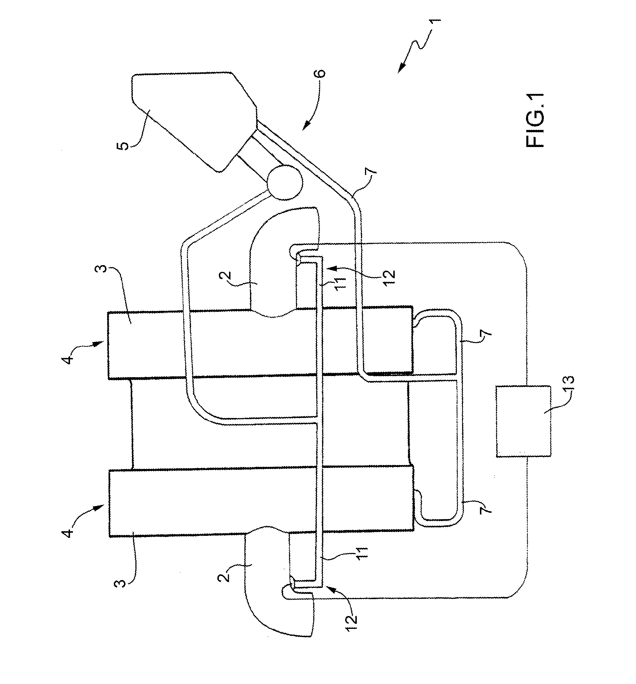
[0017]In FIG. 1, reference numeral 1 globally indicates an internal combustion engine provided with a number of intake ducts 2; each of which ends in a corresponding intake manifold 3, which is fixed to the top of a respective cylinder head 4. The internal combustion engine 1 has a lubrication oil tank 5.

[0018]Engine 1 further comprises a recirculating circuit 6, which is adapted to capture the vapors formed into heads 4 and into the oil tank 5 for introducing such vapors into the intake manifolds 2 so as to determine the controlled combustion thereof inside the cylinders.

[0019]The recirculating circuit 6 comprises a pair of recovery ducts 7, which are connected to heads 4 for capturing the vapors formed into heads 4 and are connected by a T-shaped joint for leading together into the oil tank 5; and a feed duct 11 which directly draws into the oil tank 5, splits into two feed ducts 11 by means of a T-shaped joint to lead into the intake ducts in the proximity of the intake manifolds...


PUM


Abstract

A connecting device for the fluid-tight connection of a first and a second duct provided with a connector having a fixed electrical connection terminal; a mobile electrical connector for establishing an electrical connection with the fixed electrical connection terminal; a control unit suited to check the presence of a connection between the fixed electrical connection terminal and the mobile electrical connector; and an intermediate connecting body interposed in use between the connector and the mobile electrical connector, suited to establish an electrical connection between the fixed electrical connection terminal and the mobile electrical connector and suited to allow the fixed electrical connection terminal and the mobile electrical connector to be coupled to each other, only when there is a fluid-tight joint between the two ducts.

Description

PRIORITY CLAIM AND RELATED APPLICATIONS[0001]This application claims the benefit of priority under 35 U.S.C. Section 119 to Italian Patent Application Serial No. BO2012A 000037, filed on Jan. 27, 2012, which application is incorporated herein by reference in its entirety.[0002]The present invention relates to a connecting device for the fluid-tight connection between two pipes of an internal combustion engine.BACKGROUND OF THE INVENTION[0003]Vapors (normally known by the name “blow-by gases”) are normally produced in an internal combustion engine, in the heads and / or in the oil tank during the running of the engine itself; air pollution control regulations prohibit exhaust of such vapor into the atmosphere and require that they be fed into the cylinders for controlled combustion thereof. For such reason, an internal combustion engine is provided with a recirculating circuit which is provided with a feed duct originating from the engine head or from the oil tank and connected to an i...

Claims


Application Information

Patent Timeline
IPC IPC(8): H01R13/62
CPCF16L25/01F16L37/098H01R13/62F01M13/00H01R13/005H01R13/64F16N21/00F02M25/06F16L2201/10
Inventor CECCHINELLI, GAETANO
Owner SPAN FERRARI SPA
Why Eureka
Try Eureka