
Systems and Methods for Phase Predictive Impedance Loss Model Calibration and Compensation

a phase prediction and impedance loss technology, applied in the field of electrosurgical surgery, can solve the problems of increasing heating, voltage and current measured by the sensors of the electrosurgical generator, may not equal the actual voltage and current applied to the tissue, inaccurate calculations, etc., and achieves the effect of low computational complexity

Inactive Publication Date: 2013-08-01
TYCO HEALTHCARE GRP LP
View PDF14 Cites 35 Cited by
  • Summary
  • Abstract
  • Description
  • Claims
  • Application Information

AI Technical Summary

Benefits of technology

The patent describes a system and method for accurately measuring the power and impedance of tissue. This can be done using a simple technique that requires minimal computing power and can be implemented using commonly available microprocessors, FPGAs, or DSPs. The technical effect is the ability to accurately measure important factors that can help improve the performance and reliability of medical devices that are used to treat tissue.

Problems solved by technology

Although many other variables affect the total heating of the tissue, increased current density usually leads to increased heating.
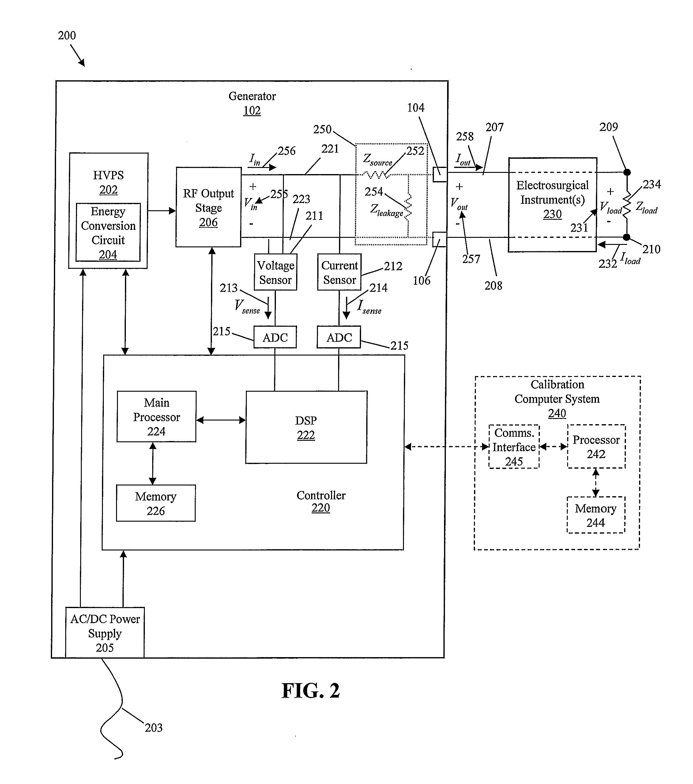
The voltage and current measured by the sensors of the electrosurgical generator, however, may not equal the actual voltage and current applied to the tissue because of RF impedance losses in the transmission line connecting the RF output stage of the electrosurgical generator to the electrodes of the electrosurgical instrument.
As a result, the power calculations may be inaccurate and may lead to improper control of the electrosurgical energy applied to the tissue.
However, this method requires greater computational complexity and more expensive high-speed hardware.

Method used


Image

  • Systems and Methods for Phase Predictive Impedance Loss Model Calibration and Compensation
  • Systems and Methods for Phase Predictive Impedance Loss Model Calibration and Compensation
  • Systems and Methods for Phase Predictive Impedance Loss Model Calibration and Compensation

Examples


Embodiment Construction

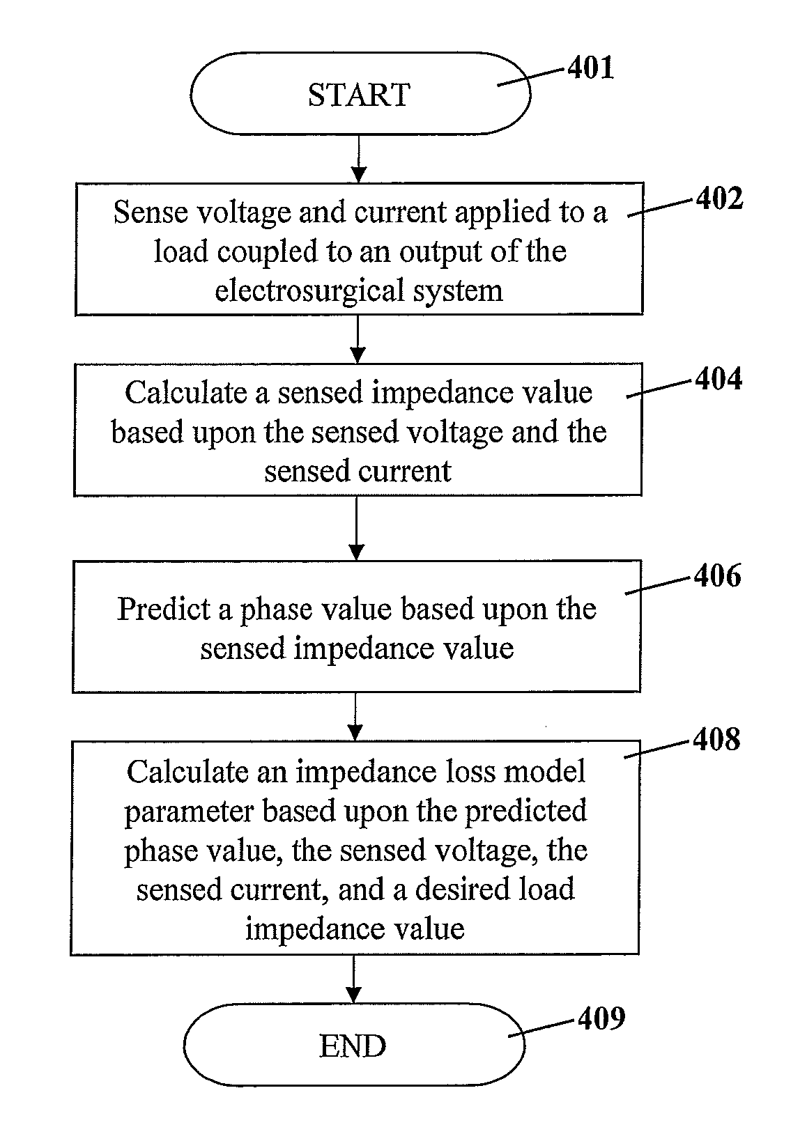
[0042]The systems and methods of the present disclosure calibrate an impedance loss model associated with the transmission lines within electrosurgical systems. These systems and methods involve sensing the voltage and current applied to a test load coupled to the output of the electrosurgical system, calculating a sensed impedance, predicting a phase between the voltage and current based upon the sensed impedance, and calculating at least one internal impedance value based upon the measured voltage and current, the predicted phase between the voltage and current, and a predetermined impedance of the test load.

[0043]The systems and methods of the present disclosure also compensate for impedance losses in the transmission lines of the electrosurgical systems using the calibrated impedance loss model. These systems and methods involve sensing a voltage and a current of an electrosurgical signal generated by and applied to a tissue site by the electro surgical system, predicting a phas...


PUM


Abstract

The systems and methods of the present disclosure calibrate impedance loss model parameters associated with an electrosurgical system having no external cabling or having external cabling with a fixed or known reactance, and obtain accurate electrical measurements of a tissue site by compensating for impedance losses associated with the transmission line of an electrosurgical device using the calibrated impedance loss model parameters. A computer system stores voltage and current sensor data for a range of different test loads and calculates sensed impedance values for each test load. The computer system then predicts a phase value for each load using each respective load impedance value. The computer system back calculates impedance loss model parameters including a source impedance parameter and a leakage impedance parameter based upon the voltage and current sensor data, the predicted phase values, and the impedance values of the test loads.

Description

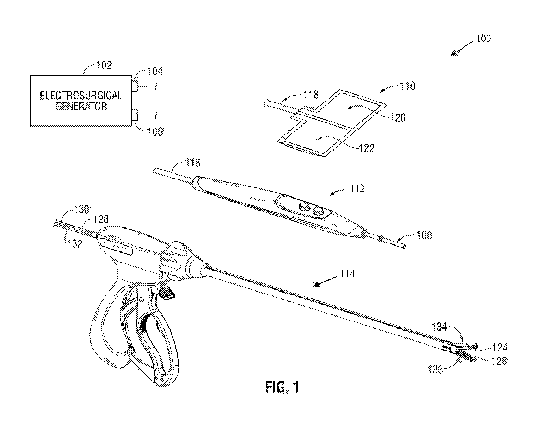
BACKGROUND[0001]1. Technical Field[0002]The present disclosure generally relates to electrosurgery. More particularly, the present disclosure relates to systems and methods for compensating for losses to obtain accurate electrical measurements in cordless or fixed-reactance cabled electrosurgical systems.[0003]2. Background of Related Art[0004]Electrosurgery involves the application of high-frequency electric current to cut or modify biological tissue during a surgical procedure. Electrosurgery is performed using an electrosurgical generator, an active electrode, and a return electrode. The electrosurgical generator (also referred to as a power supply or waveform generator) generates an alternating current (AC), which is applied to a patient's tissue through the active electrode and is returned to the electrosurgical generator through the return electrode. The alternating current typically has a frequency above 100 kilohertz to avoid muscle and / or nerve stimulation.[0005]During elec...

Claims


Application Information

Patent Timeline
Patent Type & Authority Applications(United States)
IPC IPC(8): G06F17/10
CPCA61B18/1206A61B18/1402A61B18/1445A61B2018/00755A61B2018/00178A61B2018/0075A61B2017/00725
Inventor HECKEL, DONALD W.
Owner TYCO HEALTHCARE GRP LP
Learn More