Semiconductor device and manufacturing method thereof

a semiconductor device and semiconductor technology, applied in semiconductor devices, semiconductor/solid-state device details, electrical devices, etc., can solve the problems of limiting the size of the semiconductor device becomes large, and the inability to perform simultaneous operation. , to achieve the effect of reducing the number of wiring layer formation steps

Active Publication Date: 2013-08-08
AMKOR TECH JAPAN INC
View PDF2 Cites 10 Cited by
  • Summary
  • Abstract
  • Description
  • Claims
  • Application Information

AI Technical Summary

Benefits of technology

[0050]The number of wiring layer formation steps can be reduced in the manufacture process of a multi chip package. Electrical connection with the semiconductor elements stacked via the rewiring technology is enabled. Both a metal support substrate and an organic support substrate can be used as the support substrate.

Problems solved by technology

Nevertheless, with a conventional semiconductor device obtained as described above, since only one side or both sides of the semiconductor element can be electrically connected with the support substrate since a wire bonding is used for the connection, there is a limit in that only two semiconductor elements can be simultaneously operated.
Nevertheless, the connection of the wire bonding to be connected to the semiconductor element needs to pass above the mounted semiconductor element, but if the height of the connecting member is low, it will connect with the semiconductor element and cause a short-circuit.
Thus, the size of the semiconductor device becomes large, and the junction temperatures in the semiconductor elements will increase due to the poor heat radiation of the stacked structure, thereby causing a problem in that the foregoing simultaneous operation is not possible.
Nevertheless, with POP, since the individual packages are individually assembled and the completed packages are stacked, it is difficult to reduce the assembly costs based on the reduction (shrinkage) of the semiconductor element size, and there is a problem in that the assembly cost of the stacked module is extremely expensive.
With a conventional TSV (Through Silicon Via) stacked module structure, since through-holes are provided to each of the individual semiconductor elements, there is a possibility that the semiconductor element will become damaged, and it is also necessary to add several complex and costly wafer processes of forming via electrodes in the through-holes.
Thus, this resulted in a considerable cost increase of the overall vertically stacked module.
Moreover, with the conventional structure, it is difficult to stack and mount chips of different sizes, and, due to the “addition of different rewiring layers for each layer” which is essential upon lamination of the same chips as in a memory device, the manufacture costs increase considerably in comparison to ordinary memory device modules, and there is a problem in that the cost reduction based on mass production cannot be expected.

Method used


Image

  • Semiconductor device and manufacturing method thereof
  • Semiconductor device and manufacturing method thereof
  • Semiconductor device and manufacturing method thereof

Examples


embodiment 1

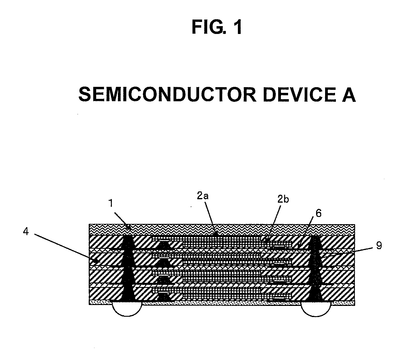
[0089]FIG. 1 is a diagram showing the configuration of Semiconductor Device A of Embodiment 1 of the present invention.

[0090]As shown in the diagram, this Semiconductor Device A includes semiconductor elements 2a, 2b, an insulating material layer 4 for sealing the semiconductor elements 2a, 2b and their peripheries, a metal thin film wiring layer 6 provided in the insulating material layer 4 and in which a part thereof is exposed on the external surface, and metal vias 9 provided in the insulating material layer and electrically connected to the metal thin film wiring layer. Reference numeral 1 represents a metal support substrate.

[0091]In addition, the two semiconductor elements 2a, 2b are stacked and provided to the insulating material layer 4, and the structure is such that one metal thin film wiring layer 6 is provided to the two semiconductor elements.

[0092]The two semiconductor elements 2a, 2b are stacked via the insulating material with the circuit surfaces thereof facing the...

embodiment 2

[0119]Semiconductor Device B of Embodiment 2 uses an organic support substrate 1′ in substitute for the metal support substrate 1 in the Semiconductor Device A of Embodiment 1 as shown in FIG. 4.

[0120]While the metal support substrate is advantageous in terms of heat-release properties and that it can be connected to GND, there are drawbacks in that the workability is inferior and hole-making is difficult, and it is difficult to provide insulation. Thus, it is difficult to mount another semiconductor package or electronic component on the metal support substrate.

[0121]Meanwhile, an organic support substrate made from an organic compound material such as glass-reinforced epoxy resin is advantageous, in comparison to a metal support substrate, in terms of favorable workability such as hole-making, and having insulating properties. Thus, as shown in FIG. 4, as a result of opening through-holes and providing electrical connection parts, it is possible to mount passive components such as...

embodiment 3

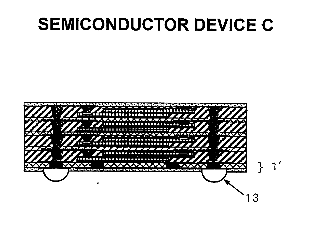
[0122]With Semiconductor Device C of Embodiment 3, as shown in FIG. 5, the organic support substrate 1′ used in Embodiment 2 is provided to the solder balls 13 mounting side.

[0123]This structure is able to achieve a face-up structure (semiconductor element circuit surfaces face the mounting face) as in the case of using wires for wiring, and it is easy to achieve the same terminal arrangement as in Embodiment 2.

[0124]Moreover, there is also an advantage in that the lower side is compatible with the motherboard since it is the organic support substrate.


PUM


Abstract

A semiconductor device containing: a semiconductor element; a support substrate; an insulating material layer for sealing the semiconductor element and a periphery thereof; a metal thin film wiring layer provided in the insulating material layer, with a part thereof being exposed on an external surface; and metal vias provided in the insulating material layer and electrically connected to the metal thin film wiring layer. The semiconductor element is provided in a plurality of units and the respective semiconductor elements are stacked via an insulating material such that a circuit surface of each semiconductor element faces the metal thin film wiring layer, and electrode pads of each semiconductor element are exposed without being hidden by the semiconductor element stacked thereabove.

Description

BACKGROUND OF THE INVENTION[0001]1. Field of the Invention[0002]The present invention relates to a semiconductor device and a manufacturing method thereof. More specifically, the present invention relates to a multi chip package-type semiconductor device having a structure in which a plurality of semiconductor chips are stacked vertically, and to the manufacturing method thereof.[0003]2. Description of the Related Art[0004]Pursuant to the recent demands for higher functionality and lighter, thinner and smaller electronic equipment, high-density integration and even high-density mounting of electronic components have advanced, and the downsizing of semiconductor devices used in the foregoing electronic equipment is also advancing than ever before.[0005]As a method of manufacturing a semiconductor device such as an LSI unit or an IC module, as shown in FIG. 10, there is a method of manufacturing a Stacked MCP (Multi Chip Package) which is obtained by foremost facing the circuit surfac...

Claims


Application Information

Patent Timeline
Patent Type & Authority Applications(United States)
IPC IPC(8): H01L23/48H01L21/50
CPCH01L2225/1023H01L2224/82031H01L2225/1035H01L2225/1029H01L2225/06524H01L2225/06589H01L2224/82039H01L2224/32245H01L2224/32225H01L2224/48091H01L2224/48145H01L2224/73265H01L24/24H01L24/82H01L25/0657H01L2224/32145H01L2224/73267H01L2224/92244H01L2924/15311H01L2225/06562H01L2225/06548H01L25/50H01L23/49816H01L23/5384H01L23/5389H01L2224/0401H01L24/97H01L2225/06586H01L2224/04105H01L2224/06135H01L2224/12105H01L2224/24226H01L2924/00014H01L2924/00015H01L2924/12042H01L2924/12044H01L2924/00H01L2924/00012H01L23/48
Inventor SAWACHI, SHIGENORIYAMAGATA, OSAMUINOUE, HIROSHIITAKURA, SATORUCHIKAI, TOMOSHIGEHORI, MASAHIKOKATSUMATA, AKIO
Owner AMKOR TECH JAPAN INC
Why Eureka
Try Eureka