Switch mode power supply for envelope tracking

a power supply and switch mode technology, applied in the direction of electric variable regulation, process and machine control, instruments, etc., can solve the problems of affecting the performance of closed loop operation, introducing significant delay, and particularly acute problem, and achieve low delay and high bandwidth

Active Publication Date: 2013-08-08
SNAPTRACK
View PDF5 Cites 62 Cited by
  • Summary
  • Abstract
  • Description
  • Claims
  • Application Information

AI Technical Summary

Benefits of technology

[0028]The invention further provides the defined switch mode power supply without limitation to an envelope tracked power supply. Thus the invention may provide a high bandwidth, low delay closed loop switch mode power supply stage comprising: a pulse width modulator for generating a width modulated pulse in dependence on an input signal and an output voltage of the switch mode power supply stage; a wideband transformer, having a winding of a first side connected to receive the modulated pulse, and a winding of a second side; and an output stage connected to the winding of the second side of the transformer, and for generating the output voltage in dependence on the modulated pulse induced in the winding of the second side.

Problems solved by technology

However the limitations of commercially available integrated circuit drivers for the driver stage 12 are such that they can introduce a significant delay (typically, with current technologies, of the order of 70 to 150 ns).
This problem is particularly acute for high voltage drivers, e.g. of the order of 50V and greater.
Moreover the delay affects the performance of the closed loop operation as it limits the maximum stable closed loop bandwidth.
The delays also mean that the fast switching speeds of an output switching stage constructed with fast transistors, such as GaN transistors, cannot be fully exploited.

Method used


Image

  • Switch mode power supply for envelope tracking
  • Switch mode power supply for envelope tracking
  • Switch mode power supply for envelope tracking

Examples


first embodiment

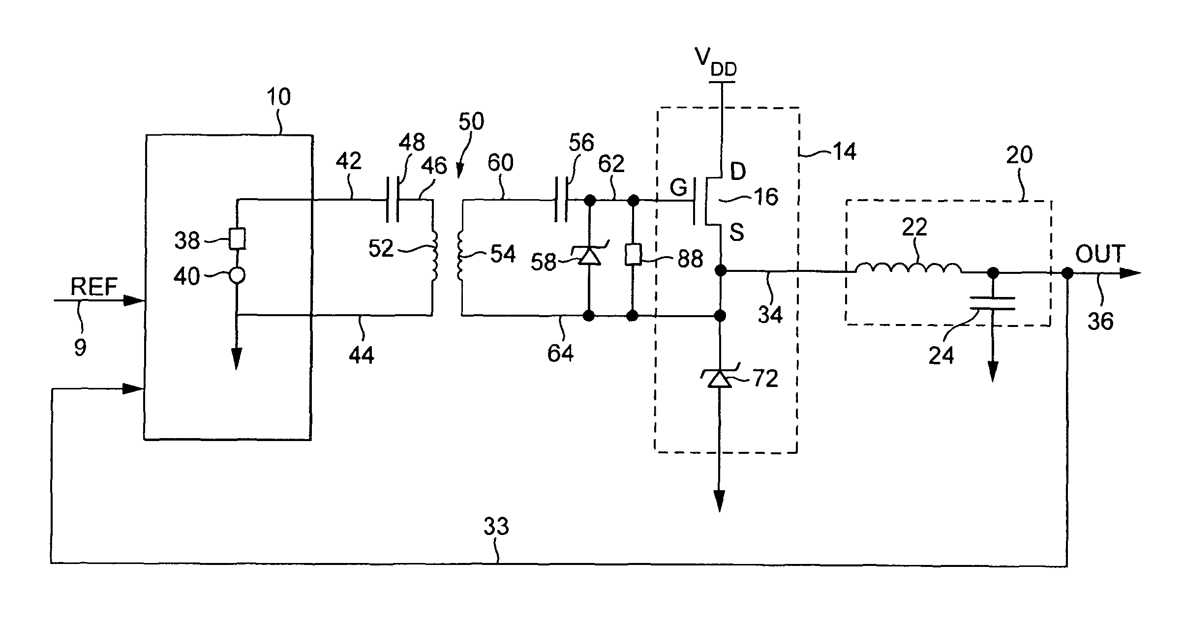
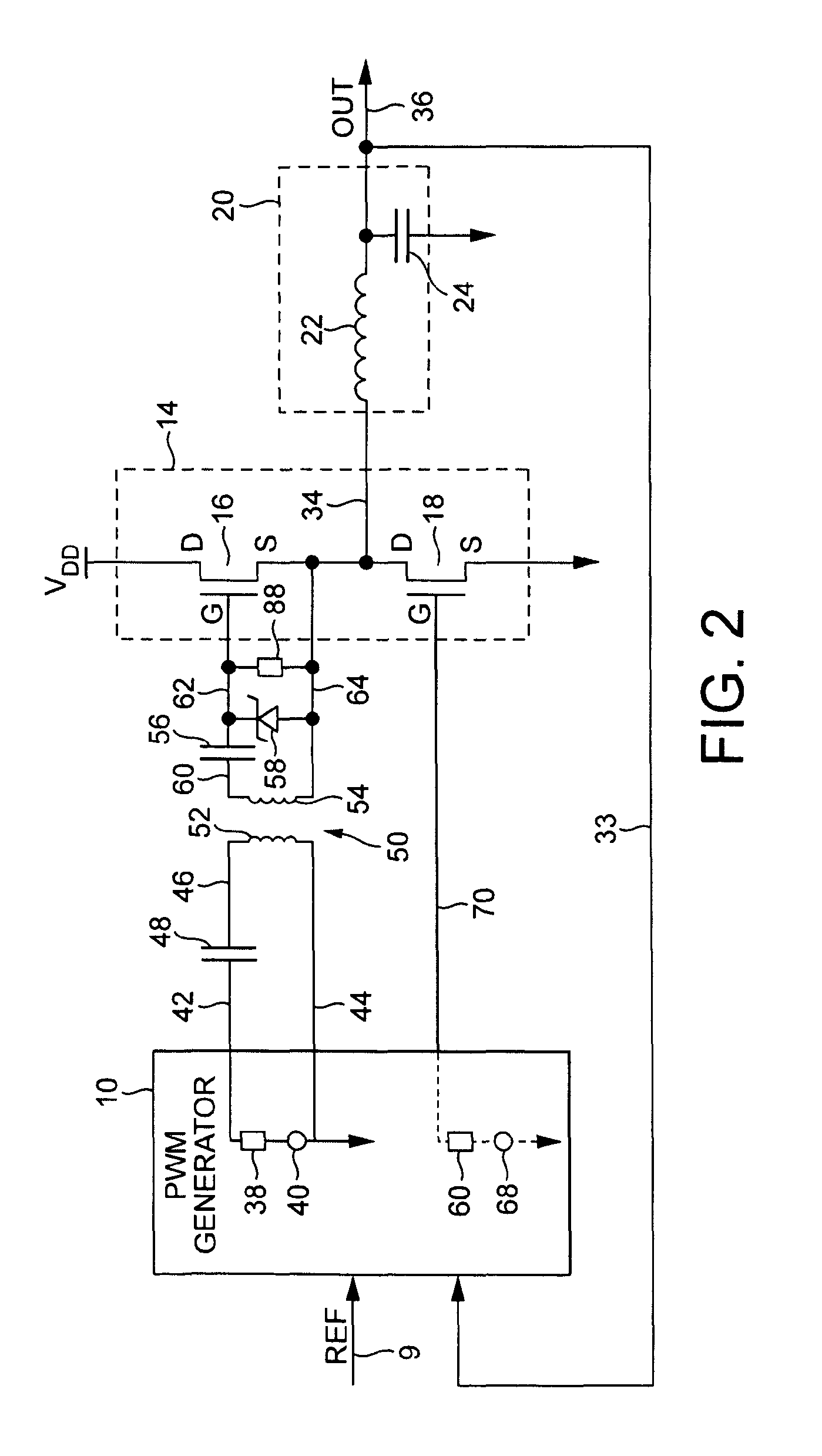
[0042]the invention is illustrated with reference to FIG. 2. In this exemplary embodiment, the output stage 14 includes the high-side FET 16 and the low-side FET 18. In general the high-side FET may be N-type or P-type. The PWM generator 10 is arranged to provide separate drive signals for the high-side and the low-side.

[0043]As illustrated, the high-side FET driver of the PWM generator may be modelled or represented as a voltage source 40 in series with a resistor 38. The resistor 38 is connected to an output line 42 of the PWM generator 10, and the voltage source 40 is connected to electrical ground. The voltage source 40 and resistor 38 provide a PWM output signal for the high-side FET 16.

[0044]As also illustrated in FIG. 2, the low-side FET driver of the PWM generator 10 may be modelled or represented as a voltage source 68 in series with a resistor 66. The resistor is connected to an output line 70 of the PWM generator 10, and the voltage source 68 is connected to electrical gr...

second embodiment

[0061]With reference to FIG. 3, a second embodiment in accordance with the invention is illustrated.

[0062]In the second embodiment of FIG. 3, the PWM generator 10 provides the PWM output signal for the first winding 52 of the transformer 50 on lines 42 and 44. The FET 18 is replaced by a diode 72, having an anode connected to electrical ground and a cathode connected to the output terminal and therefore output line 34.

[0063]The arrangement of FIG. 3 provides an alternative implementation in the output stage 14, which is implementable if the current at the output of the output stage always flows from the output stage to the load.

third embodiment

[0064]With reference to FIG. 4, a third embodiment in accordance with the invention is described.

[0065]In the arrangement of FIG. 4, the PWM generator 10 provides a single output signal on lines 42 and 44 as described with reference to FIG. 2, for delivery to the winding 52 of the first side of the transformer 50. As in FIG. 2, the portion of the output signal on line 42 is delivered to the first terminal of the winding 52 via the capacitor 48, which connects on line 46 to the terminal of the winding 52. Line 44 represents a connection to electrical ground for the voltage source 40 and the second terminal of the winding 52 as discussed with reference to FIG. 2.

[0066]In the embodiment of FIG. 4, the transformer 50 is adapted to have two windings on the second side thereof. Thus the second side of the transformer 50 includes the winding 54 as illustrated in FIG. 2, and a further winding 74. The arrangement of the winding 54 and its connection to the FET 16 is the same in FIG. 4 as des...


PUM


Abstract

There is disclosed an envelope tracked power supply comprising a high bandwidth, low delay closed loop switch mode power supply stage comprising: a pulse width modulator for generating a width modulated pulse in dependence on an input signal and an output voltage of the switch mode power supply stage; a wideband transformer, having a winding of a first side connected to receive the modulated pulse, and a winding of a second side; and an output stage connected to the winding of the second side of the transformer, and for generating the output voltage in dependence on the modulated pulse induced in the winding of the second side.

Description

BACKGROUND TO THE INVENTION[0001]1. Field of the Invention[0002]The present invention relates to an output stage of a switch mode power supply, in which a pulse width modulator generates a modulated pulse for delivery to an output switching stage via a driver stage. One or more feedback paths provide signals representative of the output of the output stage to an input of the pulse width modulator.[0003]2. Description of the Related Art[0004]With reference to FIG. 1 there is illustrated a typical prior art structure of a switch mode power supply including a pulse width modulator (PWM) generator.[0005]As illustrated in FIG. 1, there is provided a PWM generator 10, a driver stage 12, and an output stage 14 in the switch mode power supply.[0006]The PWM generator 10 generates pulse width modulated signals on a first output 26 and optionally on a second output 28, the signals on the second output being the inverse of the signals on the first output. The PWM generator 10 generates the puls...

Claims


Application Information

Patent Timeline
Patent Type & Authority Applications(United States)
IPC IPC(8): G05F1/56
CPCH02M1/08H02M3/1588H03F1/0244H03F3/2173G05F1/56H03F2200/351H03F2200/451Y02B70/1466H03F2200/102Y02B70/10H02M3/156H03F1/0238H03F3/217H02M3/158H02M3/157
Inventor WIMPENNY, GERARD
Owner SNAPTRACK
Why Eureka
Try Eureka