Unlock instant, AI-driven research and patent intelligence for your innovation.

Radio communication system, high-power base station, low-power base station, and communication control method

Inactive Publication Date: 2013-08-08
KYOCERA CORP
View PDF7 Cites 5 Cited by
  • Summary
  • Abstract
  • Description
  • Claims
  • Application Information

AI Technical Summary

Benefits of technology

The present invention provides a radio communication system, a high-power base station, a low-power base station, and a communication control method that can avoid interference between the base stations and improve overall throughput. This is achieved by limiting the use of radio resources when the low-power base station expands its coverage, allowing it to use a different resource that the high-power base station cannot use, thereby reducing interference and improving the low-power base station's throughput.

Problems solved by technology

Meanwhile, when there is overlap between radio resources used as data transmission channels of neighboring radio base stations, the data transmission channel of one of the radio base stations may receive interference from the data transmission channel of the other radio base station, and whereby the radio terminal may possibly fail to receive user data through the data transmission channel of the one radio base station.
The above problem is even worse particularly in the case of the techniques that expand the coverage of a low-power base station in a heterogeneous network, because the data transmission channel of the low-power base station is highly likely to receive great interference from the data transmission channel of a high-power base station.

Method used


Image

  • Radio communication system, high-power base station, low-power base station, and communication control method
  • Radio communication system, high-power base station, low-power base station, and communication control method
  • Radio communication system, high-power base station, low-power base station, and communication control method

Examples


first embodiment

[0050]Next, the first embodiment of the present invention will be described. The first embodiment will be described by taking, as an example, a heterogeneous network configuration designed such that picocell base stations PeNB serving as low-power base stations (low-output base stations) are placed within the communication area (macrocell) of a macrocell base station MeNB serving as a high-power base station (high-output base station).

[0051]The first embodiment will be described below through (1) Configuration of Radio Communication System, (2) Interference Control, (3) Configuration of Macrocell Base Station, (4) Configuration of Picocell Base Station, (5) Operations of Radio Communication System, and (6) Advantageous Effects of First Embodiment in this order mentioned.

(1) Configuration of Radio Communication System

[0052]FIG. 3 is a schematic configuration diagram of a radio communication system 1 according to the first embodiment.

[0053]As shown in FIG. 3, the radio communication s...

second embodiment

[0096]In the second embodiment, each picocell base station PeNB transmits information for determining the usable PDSCH resource of the macrocell base station MeNB to the macrocell base station MeNB. In the following, differences from the first embodiment will be described, and overlapping description will be omitted.

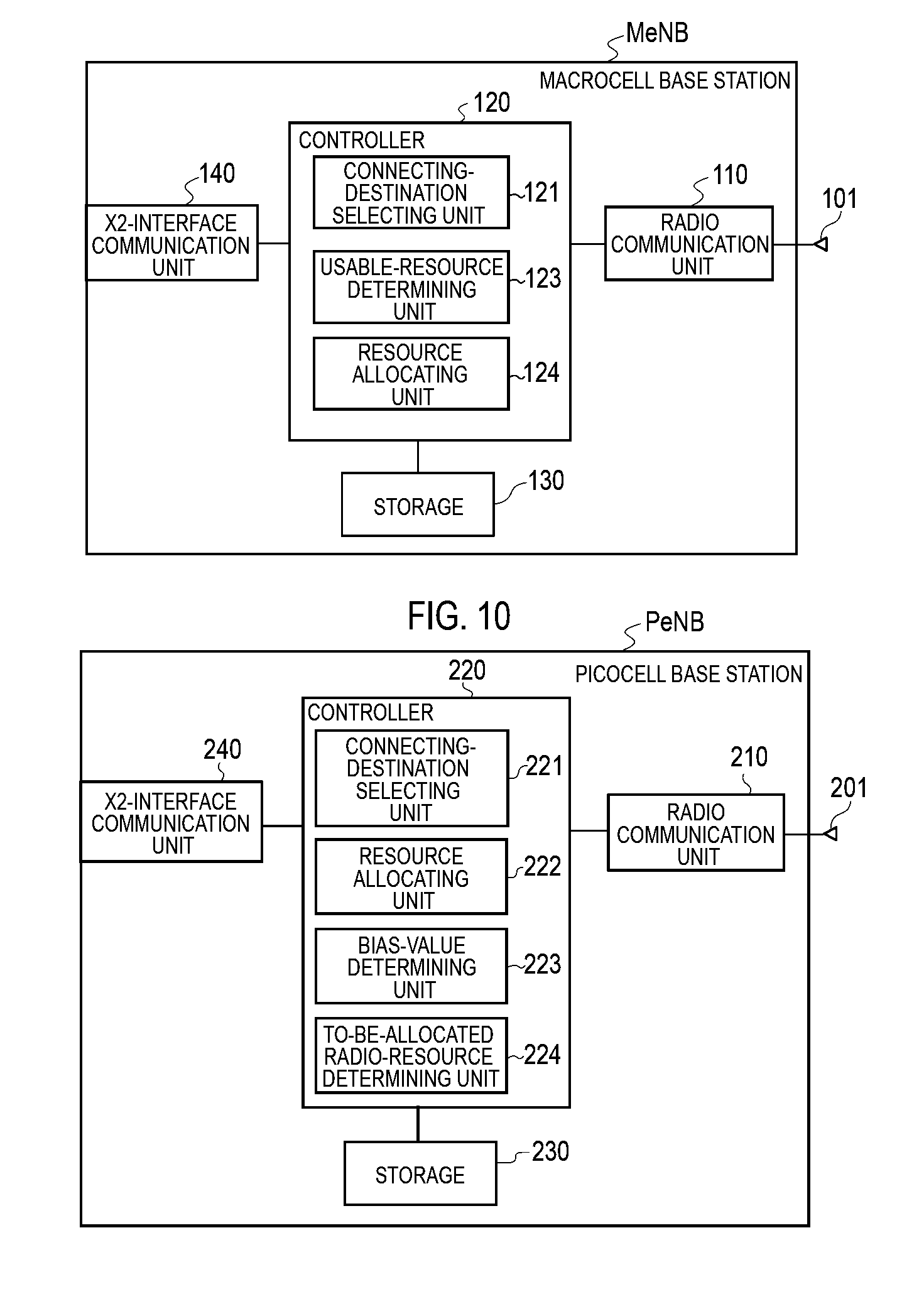
[0097]FIG. 9 is a block diagram showing the configuration of the macrocell base station MeNB according to the second embodiment. As shown in FIG. 9, the macrocell base station MeNB according to the second embodiment does not comprise the bias-value determining unit 122 described in the first embodiment.

[0098]FIG. 10 is a block diagram showing the configuration of each picocell base station PeNB according to the second embodiment. As shown in FIG. 10, each picocell base station PeNB according to the second embodiment comprises a bias-value determining unit 223 and a to-be-allocated radio-resource determining unit 224. The bias-value determining unit 223 determines the RE-...


PUM


Abstract

A radio communication system 1 comprises a picocell base station PeNB placed within a communication area of a macrocell base station MeNB and has transmission output lower than the macrocell base station MeNB. A coverage of the picocell base station PeNB is expanded. A usable resource being a radio resource which a high-power base station is allowed to use as PDSCH is determined on the basis of a degree of expansion of coverage of a low-power base station.

Description

TECHNICAL FIELD[0001]The present invention relates to a radio communication system, a high-power base station, a low-power base station, and a communication control method to which a heterogeneous network is applied.BACKGROUND ART[0002]As the next generation systems to achieve higher-speed, larger-capacity communication than the 3rd and 3.5th generation cellular radio communication systems currently in use, there are LTE (Long Term Evolution) and LTE Advanced that is an enhanced version of LTE, which are standardized by the 3GPP (3rd Generation Partnership Project) being a standardization organization.[0003]In a downlink of an LTE system (comprising LTE advanced), a radio base station transmits user data to a radio terminal by using a data transmission channel called a PDSCH (Physical Downlink Shared Channel). Note that a downlink refers to communication in a direction from a radio base station to a radio terminal whereas an uplink refers to communication in a direction from a radio...

Claims


Application Information

Patent Timeline
IPC IPC(8): H04W72/04
CPCH04W16/32H04W84/045H04W72/044H04W72/048Y02D30/70H04W72/51
Inventor NAKAMURA, KAZUTAKAOKINO, KENTANAKAYAMA, TAKU
Owner KYOCERA CORP
Features
  • R&D
  • Intellectual Property
  • Life Sciences
  • Materials
  • Tech Scout
  • Unparalleled Data Quality
  • Higher Quality Content
  • 60% Fewer Hallucinations
Learn More