Gas turbine engine fan casing having a flange for fastening pieces of equipment

a technology for gas turbine engines and fan casings, which is applied in the direction of machines/engines, stators, liquid fuel engines, etc., can solve the problem that the flange of the fan casing is only a fraction of the thickness of the flange, and the flange is made through

Active Publication Date: 2013-08-08
SN DETUDE & DE CONSTR DE MOTEURS DAVIATION S N E C M A
View PDF8 Cites 16 Cited by
  • Summary
  • Abstract
  • Description
  • Claims
  • Application Information

AI Technical Summary

Benefits of technology

[0007]A main object of the present invention is thus to mitigate such drawbacks by proposing a fan casing in which the flange enables pieces of equipment of the engine to be removed without it being ne

Problems solved by technology

Furthermore, the setback in the flange of the fan casing is

Method used


Image

  • Gas turbine engine fan casing having a flange for fastening pieces of equipment
  • Gas turbine engine fan casing having a flange for fastening pieces of equipment
  • Gas turbine engine fan casing having a flange for fastening pieces of equipment

Examples


Embodiment Construction

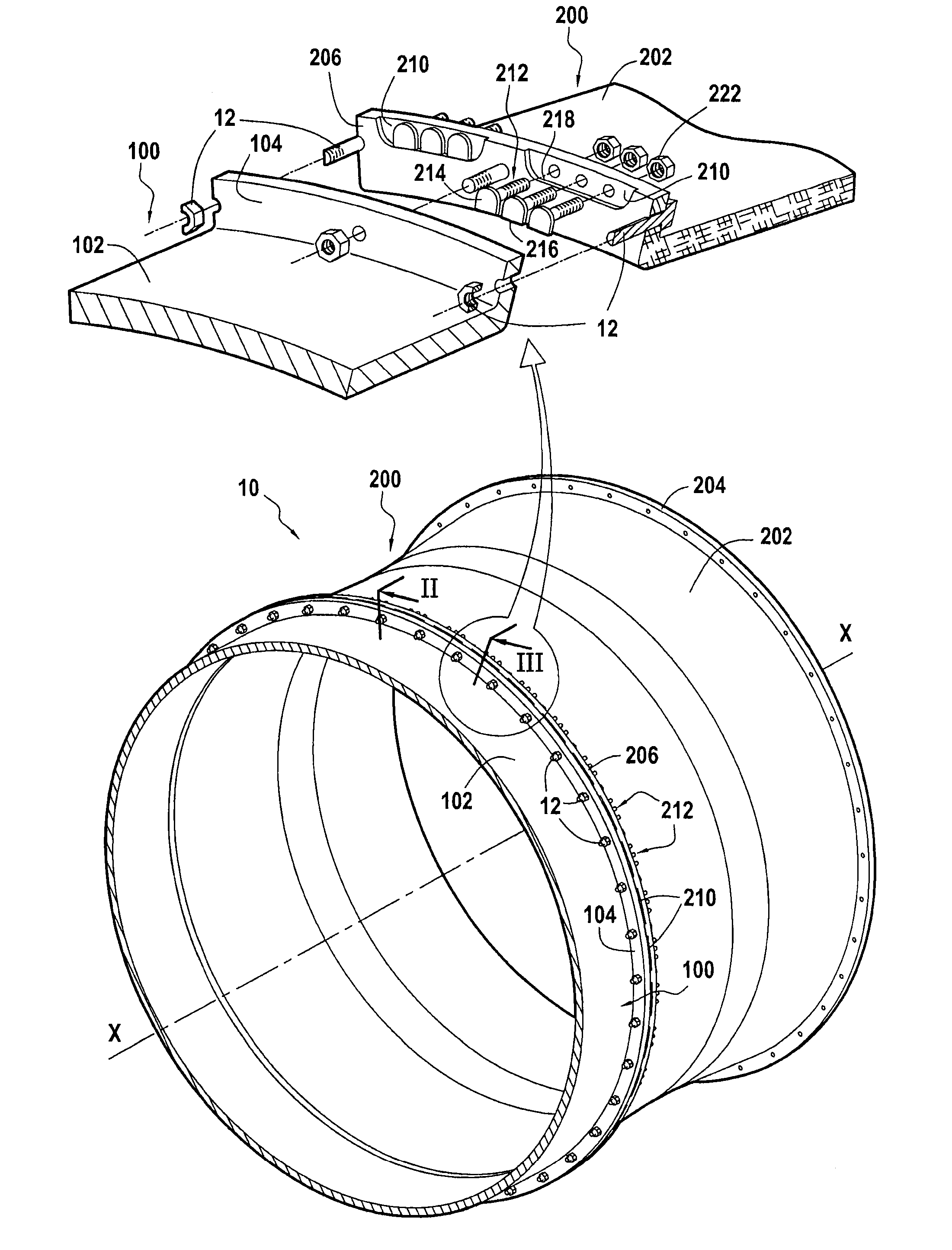
[0021]FIG. 1 shows a casing 10 within which it is possible to house a gas turbine aeroengine (not shown).

[0022]The casing 10 comprises a plurality of elements: namely in particular an air inlet sleeve 100 arranged at the inlet of the engine; and a fan casing 200 arranged downstream from the air inlet sleeve (“downstream” in the flow direction of the stream of gas passing through the engine). Each of these elements comprises a substantially cylindrical portion, respectively referenced 102 or 202, which portion is centered on a longitudinal axis X-X of the engine.

[0023]The inside surface of the cylindrical portion 102 of the air inlet sleeve 100 defines the air inlet passage into the engine. The inside surface of the cylindrical portion 202 of the fan casing serves to surround the tips of the fan blades of the engine and it incorporates or supports a retention shield (not shown).

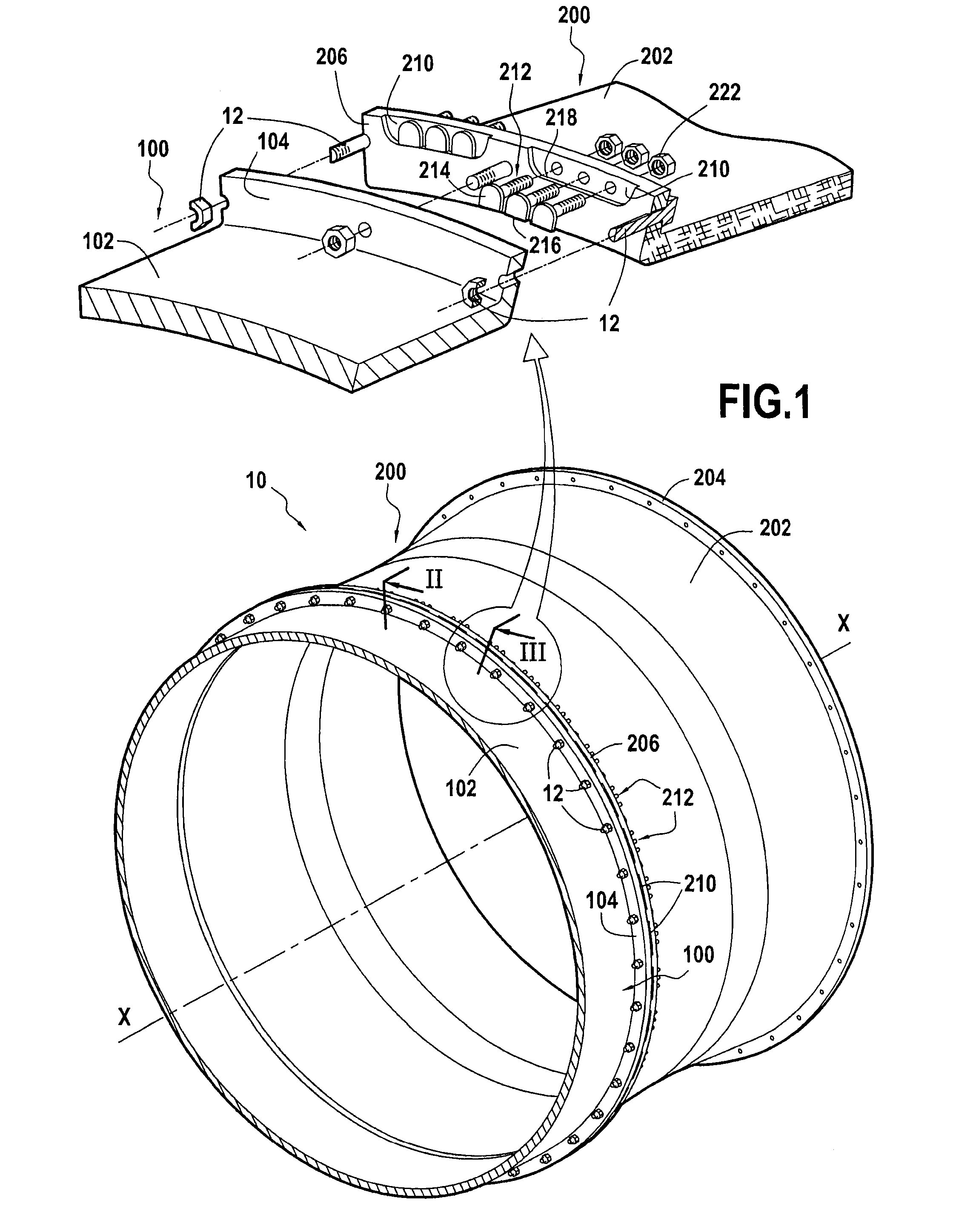
[0024]At its downstream end, the cylindrical portion 102 of the inlet sleeve 100 is terminated by an annula...


PUM


Abstract

The invention provides a fan casing for a gas turbine engine, the casing having a substantially cylindrical portion that terminates at one end in an annular flange made of composite material. The flange includes at least one setback in a fraction of its thickness and at least one bolt for fastening pieces of equipment passing right through the flange in the axial direction, the bolt for fastening pieces of equipment having a head that presents a flat that is to bear flat against a rim of the setback, and a shank forming a stud for fastening pieces of equipment on the casing.

Description

BACKGROUND OF THE INVENTION[0001]The present invention relates to gas turbine engine casings, and more particularly to fan casings made of composite material for gas turbine aeroengines.[0002]In a gas turbine aeroengine, the casing has a portion forming an air inlet sleeve with the function of defining the air inlet passage into the engine, and a portion forming a fan casing. A particular function of the fan casing is to retain debris, such as articles that have been ingested or fragments of damaged blades, which debris is projected by centrifugal force and needs to be prevented from passing through the casing and reaching other portions of the aircraft. The fan casing also supports a certain number of pieces of equipment of the engine, such as harnesses for fastening pipes conveying de-icing liquid or supports for fastening the electronic control unit of the engine.[0003]In known manner, the air inlet sleeve and the fan casing have annular flanges at their axial ends serving in par...

Claims


Application Information

Patent Timeline
IPC IPC(8): F01D25/24
CPCF05D2300/603F05D2260/31Y02T50/672F02K3/06F02C7/32F01D25/243Y02T50/60F01D25/28F04D29/522F04D29/601
Inventor GAUDRY, FLORIANELISSEEFF, TIMOTHEEIMBOURG, FREDERICRATTE, GUILLAUME
Owner SN DETUDE & DE CONSTR DE MOTEURS DAVIATION S N E C M A
Why Eureka
Try Eureka