Electrode for measuring bio potential, method of manufacturing the electrode, and system for measuring physiological signal

a bio-potential and electrode technology, applied in the field of electrodes for measuring bio-potentials, a method of manufacturing electrodes, and a system for measuring physiological signals, can solve problems such as power consumption, technical problems that need to be resolved, and respect to measurement accuracy

Active Publication Date: 2013-08-08
SAMSUNG ELECTRONICS CO LTD
View PDF14 Cites 5 Cited by
  • Summary
  • Abstract
  • Description
  • Claims
  • Application Information

AI Technical Summary

Benefits of technology

[0010]FIG. 2 illustrates an example of noise generated in a measured physiological signal due to a change in an interface caused by a movement of a body, and shows that a signal-to-noise ratio (SNR) of the measured physiological signal is reduced by the movement of the body.
[0009]In order to always have a physiological signal measuring system on a living body in daily life, an area of an electrode that is in contact with the skin of the body needs to be minimized to reduce skin irritation. In addition, it is necessary to reduce motion artifacts to accurately measure physiological signals during exercise.
[0003]This disclosure relates to an electrode for measuring a bio potential, a method of manufacturing the electrode, and a system for measuring a physiological signal.

Problems solved by technology

In daily life, in order for an electrode for a living body to be attached to the living body of a user and to measure physiological signals of the user all of the time, various technical problems with respect to accuracy of measurement, communication, power consumption, and the technical problems need to be resolved.

Method used


Image

  • Electrode for measuring bio potential, method of manufacturing the electrode, and system for measuring physiological signal
  • Electrode for measuring bio potential, method of manufacturing the electrode, and system for measuring physiological signal
  • Electrode for measuring bio potential, method of manufacturing the electrode, and system for measuring physiological signal

Examples


Embodiment Construction

[0049]The following detailed description is provided to assist the reader in gaining a comprehensive understanding of the methods, apparatuses, and / or systems described herein. However, various changes, modifications, and equivalents of the methods, apparatuses, and / or systems described herein will be apparent to one of ordinary skill in the art. Also, descriptions of functions and constructions that are well known to one of ordinary skill in the art may be omitted for increased clarity and conciseness.

[0050]Throughout the drawings and the detailed description, the same reference numerals refer to the same elements. The drawings may not be to scale, and the relative size, proportions, and depiction of elements in the drawings may be exaggerated for clarity, illustration, and convenience.

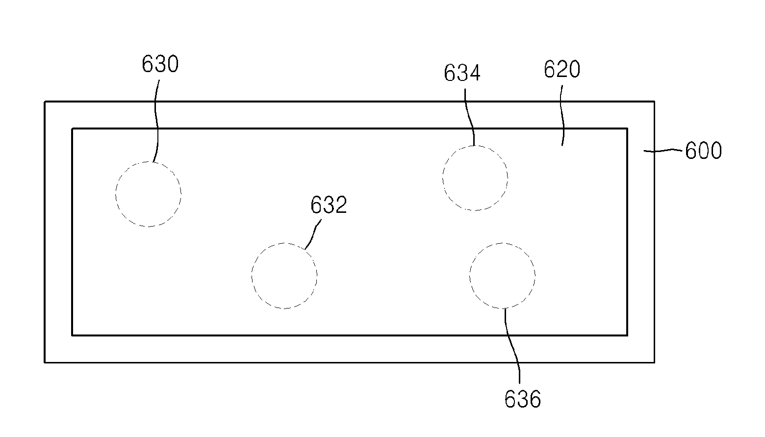
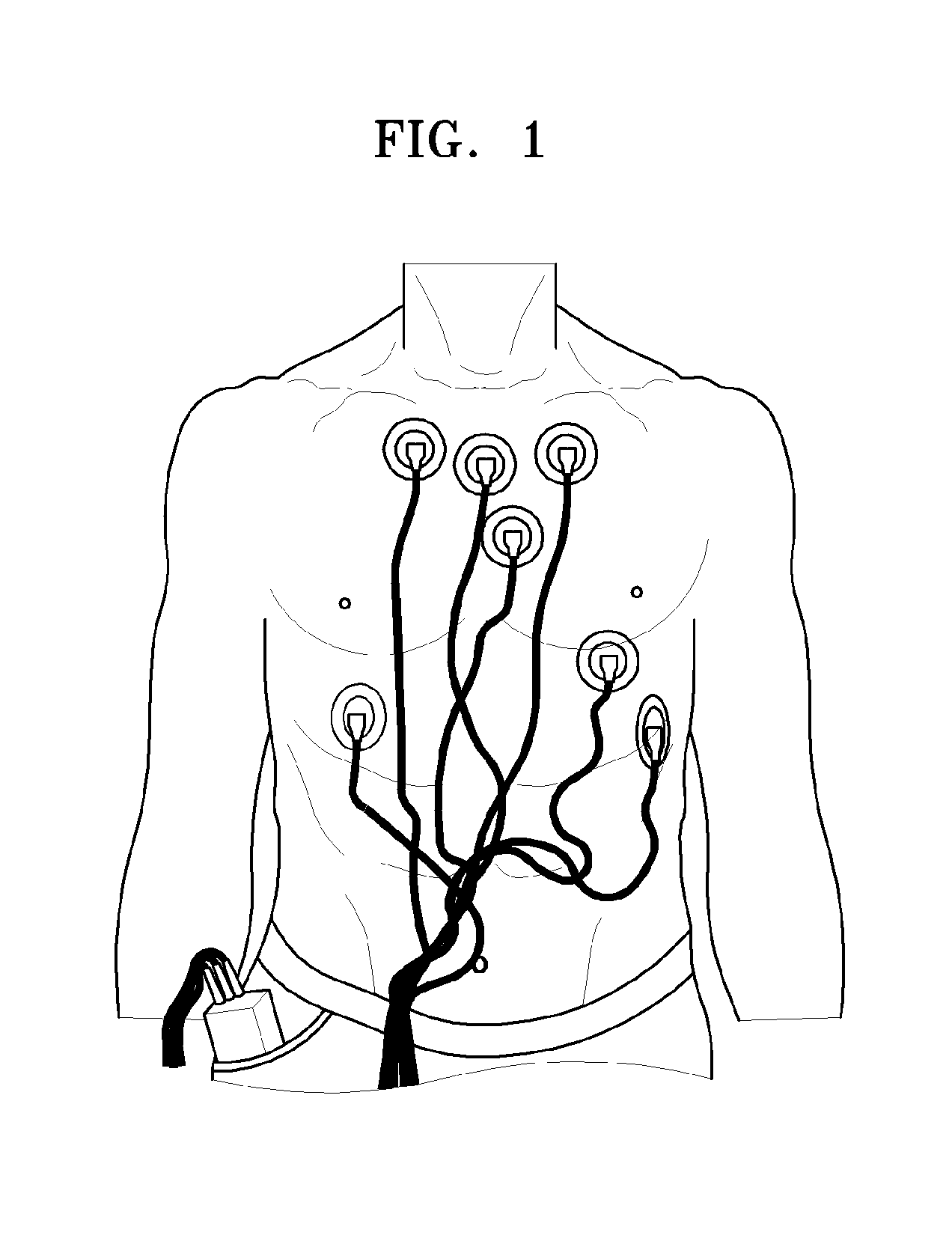
[0051]An apparatus for measuring a physiological signal includes an electrode for a living body that is attached to a human body, and a sensing platform that is attached to the electrode for a living...


PUM

PropertyMeasurementUnit
impedancesaaaaaaaaaa
areaaaaaaaaaaa
thicknessaaaaaaaaaa

Abstract

An electrode for measuring a bio potential includes a conductive adhesive having one side configured to have at least two metal electrodes attached thereto while the electrode is being used, and another side configured to be attached to a living body while the electrode is being used, the conductive adhesive having a predetermined area and a predetermined thickness; and a supporting element configured to support the conductive adhesive while the conductive adhesive is attached to the living body; wherein an impedance is formed between the at least two metal electrodes while the at least two metal electrodes are attached to the side of the conductive adhesive, the impedance depending on a thickness of the conductive adhesive and having a value that prevents the at least two metal electrodes from being shorted together.

Description

CROSS-REFERENCE TO RELATED APPLICATIONS[0001]This application claims the benefit of Korean Patent Application No. 10-2012-0012528 filed on Feb. 7, 2012, in the Korean Intellectual Property Office, the disclosure of which is incorporated herein by reference in its entirety for all purposes.BACKGROUND[0002]1. Field[0003]This disclosure relates to an electrode for measuring a bio potential, a method of manufacturing the electrode, and a system for measuring a physiological signal.[0004]2. Description of Related Art[0005]Recent healthcare systems improve accuracy and convenience of diagnosis by measuring various physiological signals in daily life. In particular, smart healthcare systems for providing health-related services through personal health information databases, helping medical staff to perform telediagnoses, and delivering results of diagnoses and prescriptions to patients are being introduced.[0006]A human body is a conductor in which an electrical field is formed due to an a...

Claims


Application Information

Patent Timeline
Patent Type & Authority Applications(United States)
IPC IPC(8): A61B5/04H01R43/16A61B5/0408A61B5/296
CPCA61B5/04A61B5/04087H01R43/16A61B5/6832Y10T29/4921A61B5/0488A61B5/0496A61B5/0533A61B2562/0209A61B5/0478A61B2562/0217A61B2562/0215A61B5/259A61B5/291A61B5/389A61B5/398A61B5/263A61B5/25A61B5/7225A61B2562/125A61B5/296
Inventor KO, BYUNG-HOONLEE, TAK-HYUNGKIM, YOUN-HOSHIN, KUN-SOO
Owner SAMSUNG ELECTRONICS CO LTD
Why Eureka
Try Eureka