Optical force sensing element and microsurgical instrument

a technology of optical force and sensing element, which is applied in the field of optical force sensing element for microsurgical instruments to achieve the effects of low manufacturing cost, low cost, and high accuracy of sensing elemen

Active Publication Date: 2013-08-08
SENSOPTIC
View PDF45 Cites 10 Cited by
  • Summary
  • Abstract
  • Description
  • Claims
  • Application Information

AI Technical Summary

Benefits of technology

[0018]The problem to be solved is to describe an optical force sensing element for microsurgical instruments as described in the technical field of the invention, being manufactured at low cost and having a sensitivity which is 5 to 20 times higher in the z-direction axis of the structure than in the directio

Problems solved by technology

A further problem is to describe a microsurgical instrument for middle-ear s

Method used


Image

  • Optical force sensing element and microsurgical instrument
  • Optical force sensing element and microsurgical instrument
  • Optical force sensing element and microsurgical instrument

Examples


Embodiment Construction

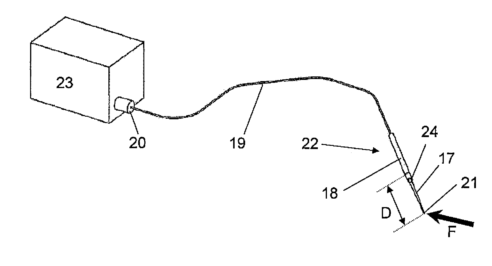
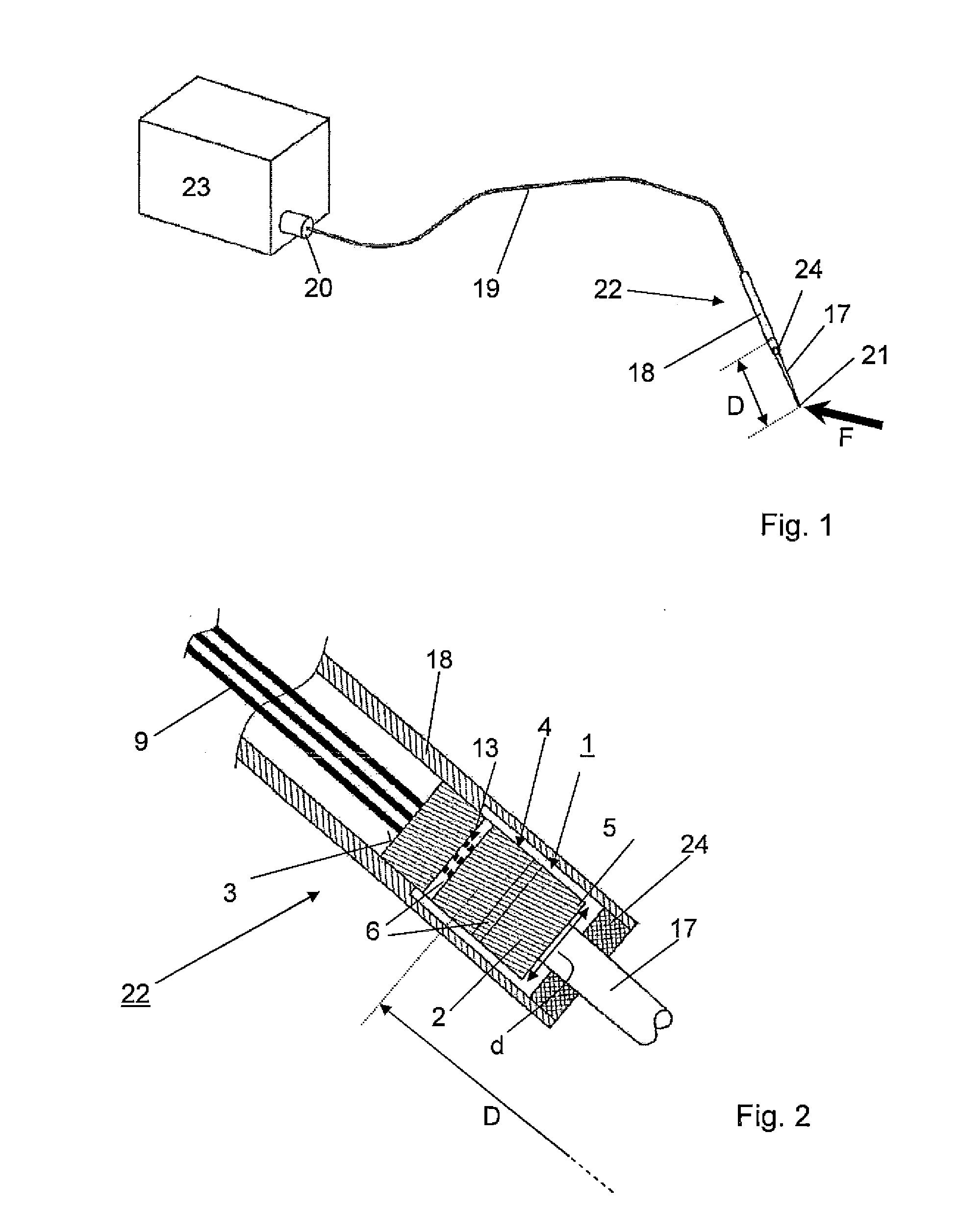
[0030]The invention is described referring to the figures. FIG. 1 shows a schematic view of a microsurgical instrument 22 according to the present invention connected through optical fibres 9 in a cable 19 with a connector 20 to an evaluation unit 23, which is for example an opto-electronics unit composed of WLI signal conditioners for the reading of a gap lengths of Fabry-Perot-cavities and a microprocessor or computer for the computation of the force vector. The microsurgical instrument 22 can be hand-held by the surgeon or controlled by an automatic robotic system on its housing 18 containing an optical force sensing element 1 (FIG. 2). It further comprises a long and thin shaft 17 with a tip 21 which is attached to the optical force sensing element 1 (FIG. 2) in the housing 18. The total distance between the centre of the sensing element 1 and the tip 21 of the shaft 17 is the length D (FIG. 2). During use a three dimensional force Fxyz is applied at the tip 21 and registered at...


PUM

PropertyMeasurementUnit
Thicknessaaaaaaaaaa
Angleaaaaaaaaaa
Angleaaaaaaaaaa

Abstract

An optical force sensing element for microsurgical instruments and methods measures force F in three orthogonal directions and includes a monolithic cylinder structure, a cylindrical surface and a top surface that absorbs and transmits the force F. Three punch-like notches, all being parallel to the y-direction, are spaced apart along the z-axis and form two blades between the first and second notch and between the second and the third notch. Three channels parallel to the z-axis extend from the bottom surface to the top surface and cross the first notch while bypassing the other two notches. Three optical fibres, each fixed in one of the three channels, all entering the structure from the bottom surface, cross the first notch and end at or near the top surface while being interrupted in the first notch and forming two surfaces of each fibre that define a Fabry-Perot interferometric cavity.

Description

CROSS-REFERENCE TO RELATED APPLICATIONS[0001]This application claims priority to Swiss Application Serial No. 00164 / 12 filed Feb. 7, 2012.FIELD OF THE INVENTION[0002]The invention relates to an optical force sensing element for microsurgical instruments, for measuring force F in three orthogonal directions x, y, z, comprising a monolithic cylinder structure with a bottom surface expanding in a plane x-y, an axis in direction z, a cylindrical surface surrounding the axis z and a top surface opposite the bottom surface suitable to absorb and transmit the force F to be measured.BACKGROUND[0003]In the field of minimally invasive microsurgery and therapy, in-vivo feedback information about the contact force exerted at the tip of instruments or tools is an important parameter required by surgeons to improve the outcome of their interventions. Frequently, the reduced access conditions affect the feel of interaction forces between the instruments and the tissues or organs being treated, and...

Claims


Application Information

Patent Timeline
IPC IPC(8): A61B6/00B23P11/00
CPCG01L5/166A61B19/46Y10T29/49826A61B2017/00526A61B2019/464A61B2017/00057A61B90/06A61B2090/064
Inventor BERTHOLDS, AXELLLOSAS, PEREHENEIN, SIMON
Owner SENSOPTIC
Why Eureka
Try Eureka