Total Knee Replacement Implant Based on Normal Anatomy and Kinematics

a total knee and implant technology, applied in the field of knee implants, can solve the problems of extreme manufacturing tolerances, and achieve the effects of promoting edge loading, high flexion, and avoiding excessive edge loading

Active Publication Date: 2013-08-08
NEW YORK UNIV
View PDF6 Cites 15 Cited by
  • Summary
  • Abstract
  • Description
  • Claims
  • Application Information

AI Technical Summary

Benefits of technology

[0008]An artificial knee where the femoral component is presented that is derived directly from anatomic shapes, including the femoral trochlea, the lateral bearing surface, the medial bearing surface, and the intercondylar area between them. All of the bearing surfaces are smoothly connected. Certain dimensions and radii are specified as representing key dimensional parameters for the composite surface. The tibial component comprises a bearing surface that is generated from a multiplicity of femoral component positions that represent the average neutral path of knee motion and the laxity about the neutral path. Specified modifications are made to the anatomical motion to avoid excessive edge loading of the femoral component on the tibial component at the extremes of motion. An algorithm for modification of the multiple femoral components is shown, for the purpose of providing appropriate dishing and restraint of excessive motions. The tibial surface generated in the above manner would have a close fit with the femoral surface, which has the disadvantage of requiring extreme manufacturing tolerances, and would also promote edge loading for eccentric loading conditions. To alleviate these problems, an algorithm is shown for modifying the tibial surface to allow appropriate clearances with the femoral surface. One important feature of the tibial surface is a relief on the posterior medial side, which is an imprint of the posterior of the implant and of the posterior femoral condyles in high flexion. This provides clearance to facilitate such flexion and avoid impingement on the plastic. A further tibial feature is the central area which is generated by the intercondylar area of the femoral component. This raised hump on the tibial surface provides motion guidance and stability in multiple directions and at multiple positions in the flexion arc.

Problems solved by technology

The tibial surface generated in the above manner would have a close fit with the femoral surface, which has the disadvantage of requiring extreme manufacturing tolerances, and would also promote edge loading for eccentric loading conditions.

Method used


Image

  • Total Knee Replacement Implant Based on Normal Anatomy and Kinematics
  • Total Knee Replacement Implant Based on Normal Anatomy and Kinematics
  • Total Knee Replacement Implant Based on Normal Anatomy and Kinematics

Examples


Embodiment Construction

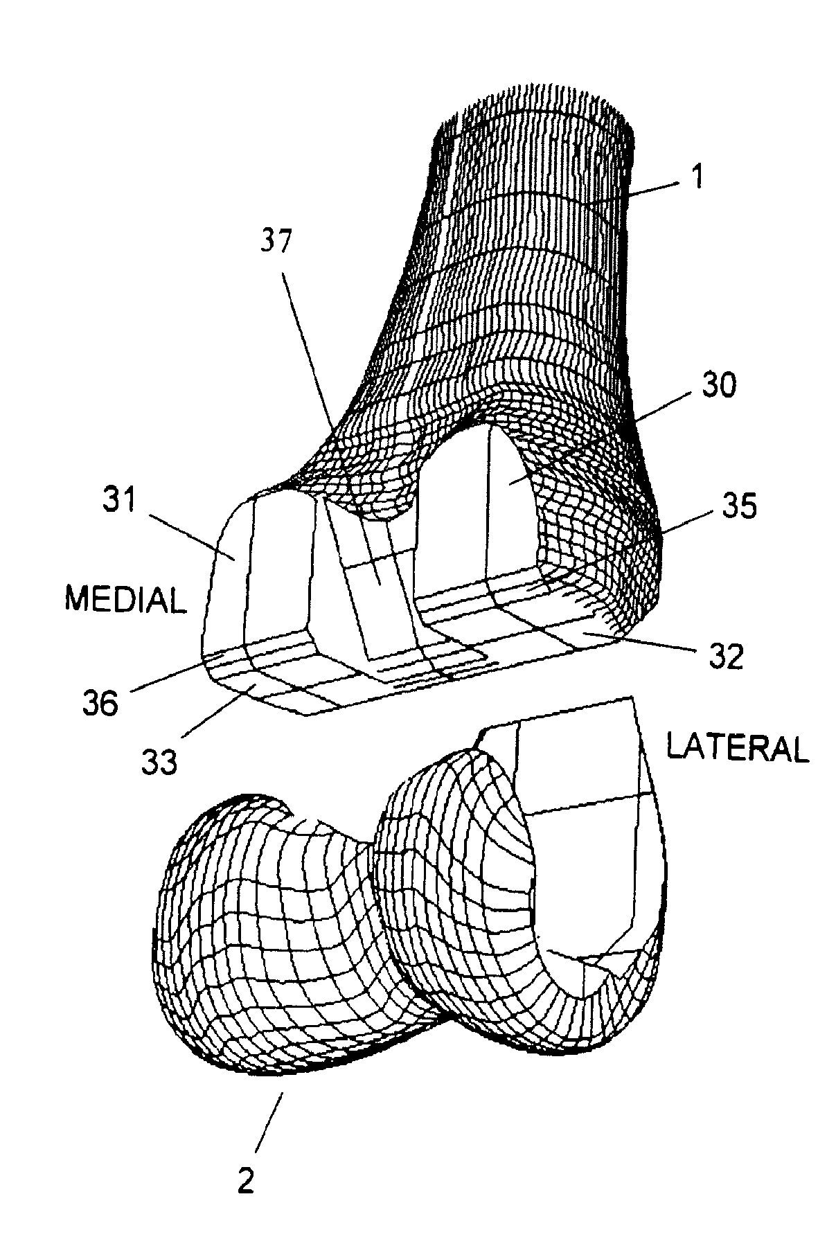
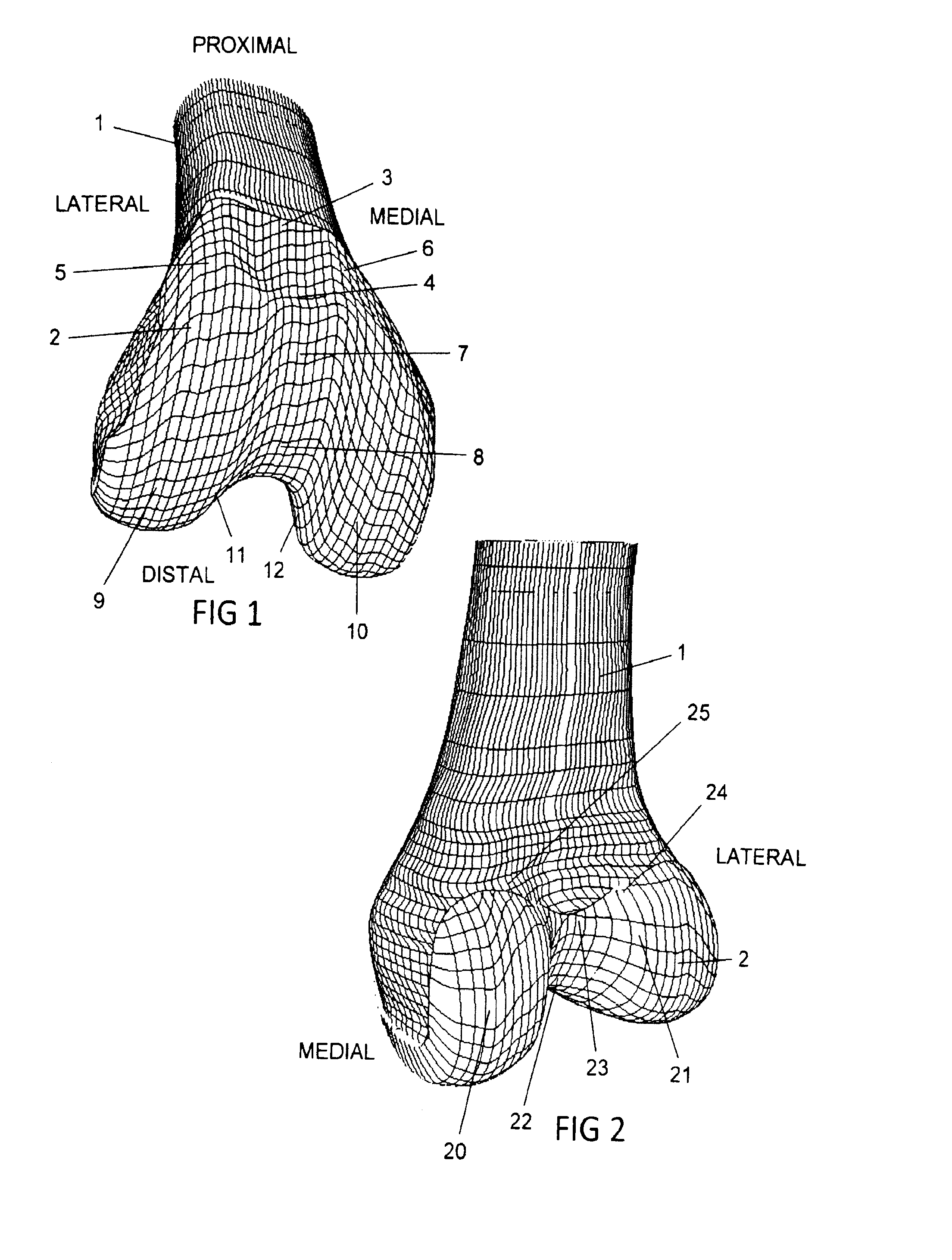
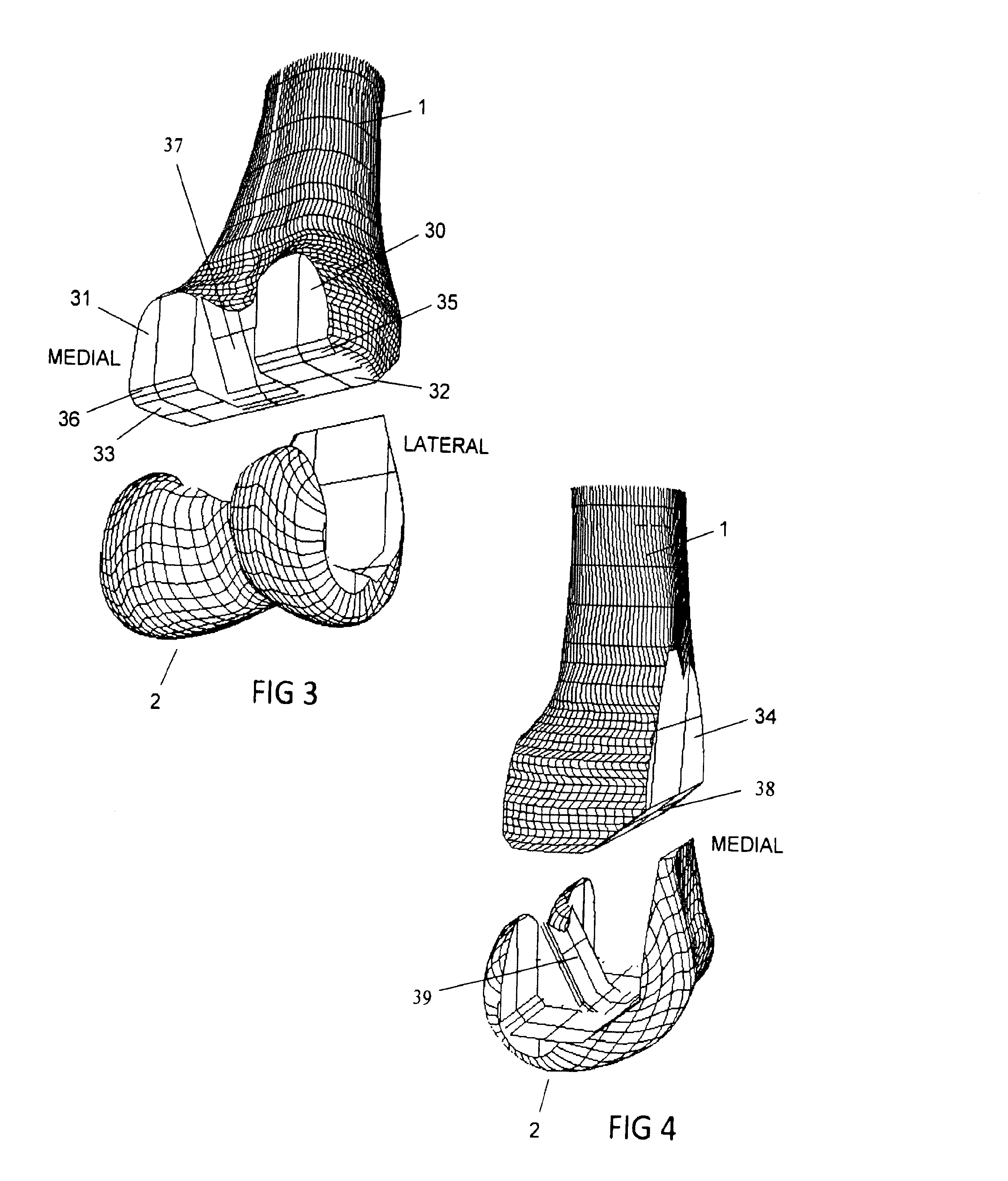
[0024]In FIGS. 1 and 2, the distal femur 1 is shown with the femoral component 2 fixed in place. The outer bearing surface of the femoral component is a replica of the anatomic distal femur for the purpose of illustration, but this can be modified slightly for purposes of smoothing, making surfaces of definable geometrical parameters, or manufacturability.

[0025]A baseline anatomically representative femur is defined as a femoral prosthesis comprising a distal bearing surface that duplicates that of an anatomic femur. The distal bearing surface shape can be taken from an individual natural femur. Alternatively, it can also be an average shape determined for a collection of cadaveric knees. It can also be an average shape determined from a collection of MRI scans, either normal knees, or knees with some degeneration as seen in osteoarthritis. The averaging method can either be by a scaling process followed by the definition of numerous sagittal slices and then averaging the slices, fr...


PUM


Abstract

A total knee replacement prosthesis is presented whose bearing surfaces are derived from an anatomically representative femur and a modified baseline tibial surface. The contacting femoral and tibial bearing surfaces comprise the inter-condylar as well as condylar regions.

Description

PRIORITY CLAIM TO PREVIOUS PATENT APPLICATIONS[0001]This non-provisional U.S. patent application, under 35 U.S.C. 371, claims the benefit of priority from PCT application, PCT / US11 / 55764, filed 11 Oct. 2011, that claims priority from U.S. Provisional Patent Application No. 61 / 392,172, filed 12 Oct., 2010, and U.S. Provisional Patent Application No. 61 / 454,023, filed 18 Mar. 2011, the entire disclosures of which are incorporated by reference in their entirety.BACKGROUND OF THE INVENTION[0002]1. Field of the Invention[0003]The present invention generally relates to knee implant where the femoral component is derived directly from anatomic shapes, including the femoral trochlea, the lateral bearing surface, the medial bearing surface, and the intercondylar area between them.[0004]2. Description of the Related Art[0005]The first condylar replacement type of total knee replacement intended for cruciate resection was the Freeman-Swanson (Freeman, Swanson, Todd 1977), designed in the late ...

Claims


Application Information

Patent Timeline
Patent Type & Authority Applications(United States)
IPC IPC(8): A61F2/38
CPCA61F2/38A61F2002/30952A61F2002/30948A61F2/3886
Inventor WALKER, PETER STANLEY
Owner NEW YORK UNIV
Why Eureka
Try Eureka