Asymmetric exhaust gas recirculation system

a recirculation system and exhaust gas technology, applied in the direction of machines/engines, mechanical equipment, non-fuel substance addition to fuel, etc., can solve the problems of increasing the complexity of controlling two, increasing the complexity of engine control, increasing the cost, etc., to reduce the number of components and sensors used in the egr system, the effect of reducing the cost and reducing the cos

Active Publication Date: 2013-08-15
FORD GLOBAL TECH LLC
View PDF12 Cites 7 Cited by
  • Summary
  • Abstract
  • Description
  • Claims
  • Application Information

AI Technical Summary

Benefits of technology

[0006]In this way, the number of components and sensors used in the EGR system may be reduced leading to decreased cost. Further, greater flexibility in packaging of low-pressure EGR systems may be achieved and engine control complexity in operating the EGR system may be reduced. Additionally, in such a configuration, a positive crankcase ventilation (PCV) system can be coupled to

Problems solved by technology

However, the inventors herein have recognized issues with approaches which utilize separate low-pressure EGR systems for each turbocharger in a twin turbocharged engine.
For example, using separate EGR systems may result in dual sets of EGR components and sensors leading to increased cost, packaging issues, and an increase in engine control complexity.
For example, imbalanc

Method used


Image

  • Asymmetric exhaust gas recirculation system
  • Asymmetric exhaust gas recirculation system
  • Asymmetric exhaust gas recirculation system

Examples


Embodiment Construction

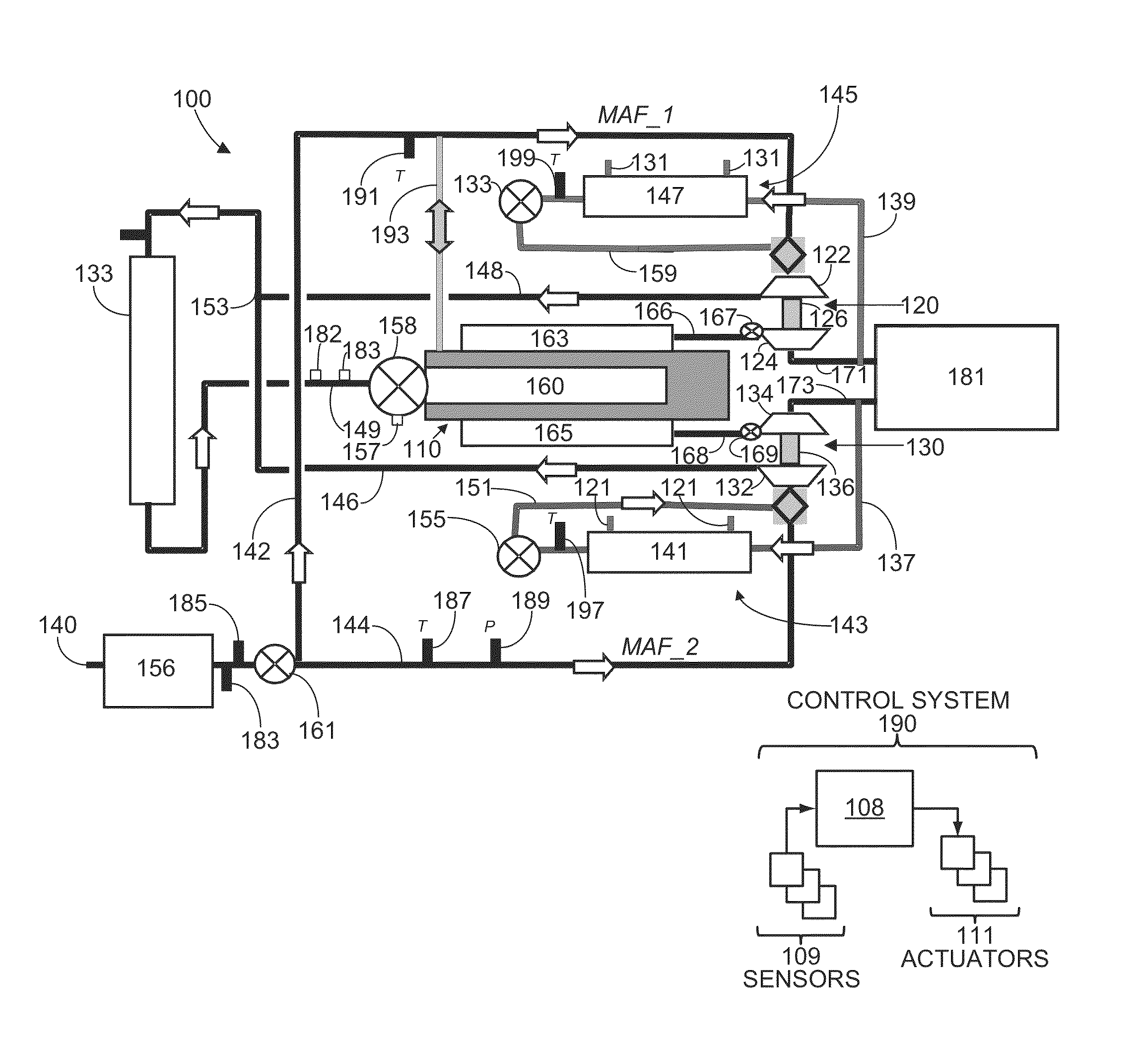
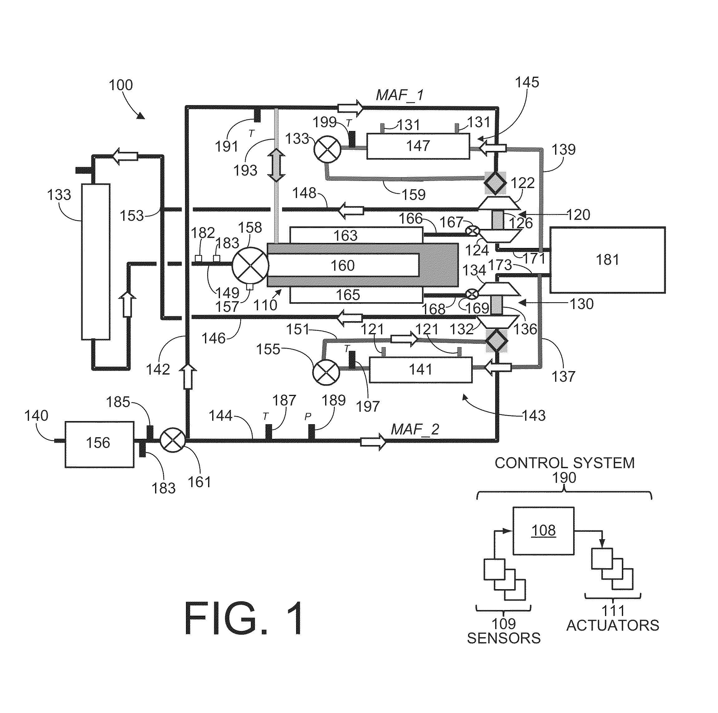
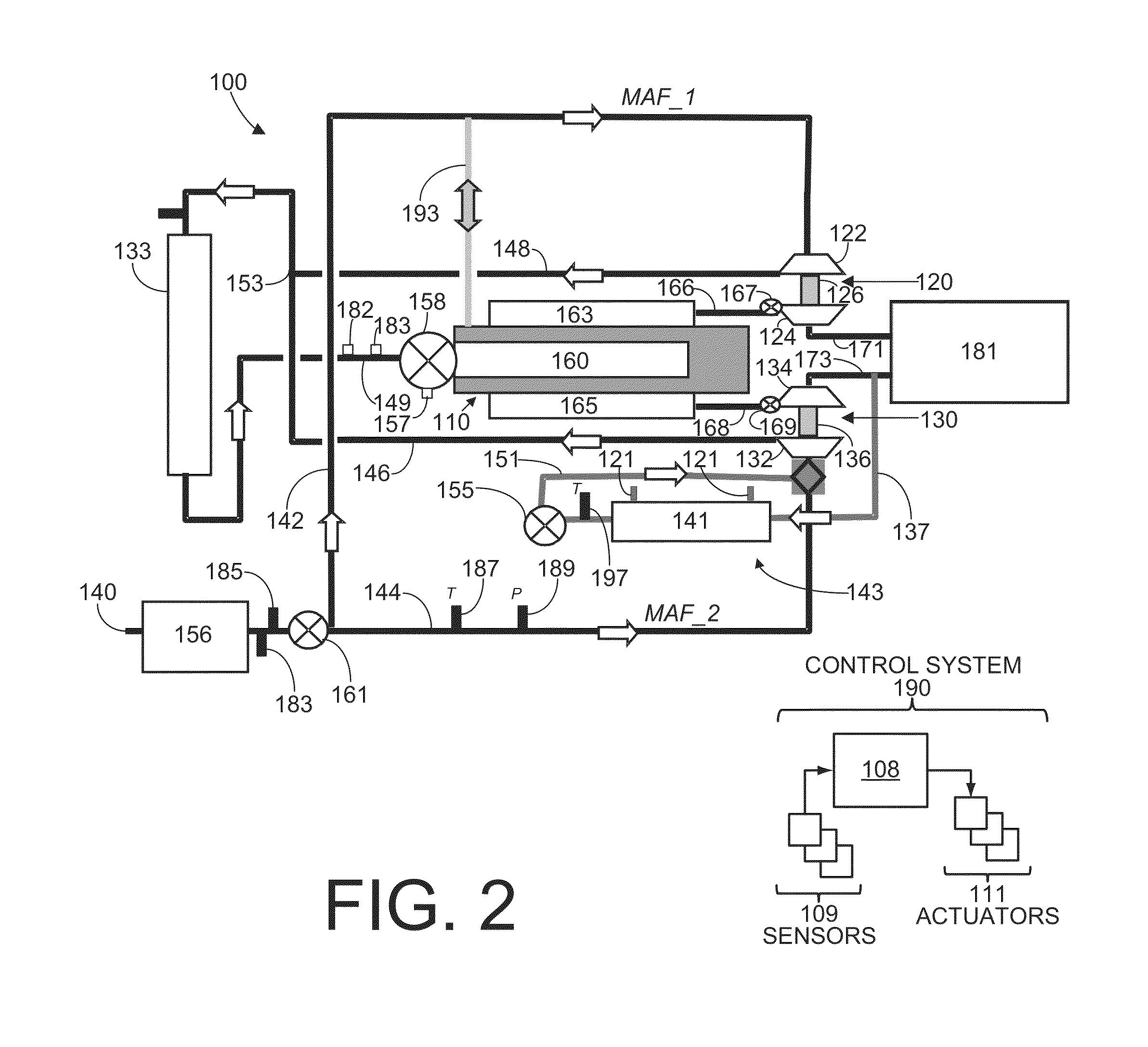
[0012]Systems and methods for a twin turbocharged engine with a single exhaust gas recirculation (EGR) system are disclosed. As remarked above, the inventors herein have recognized various issues with approaches which utilize separate low-pressure EGR systems for each turbocharger in a twin turbocharged engine, such as shown in FIG. 1. In contrast, FIGS. 2-3 and show example twin turbocharger engine systems which utilize a single EGR system and FIG. 4 shows an example method for directing air and exhaust gasses in such systems.

[0013]FIG. 1 shows a schematic depiction of an example engine system 100 including a multi-cylinder internal combustion engine 110, twin turbochargers 120 and 130, and exhaust gas recirculation (EGR) systems 145 and 143. As one non-limiting example, engine system 100 can be included as part of a propulsion system for a vehicle. Engine 110 may be any suitable type of engine; e.g., a gasoline engine, a diesel engine, a hybrid engine, etc.

[0014]Engine system 100 ...


PUM


Abstract

Systems and methods for a twin turbocharged engine with a single exhaust gas recirculation (EGR) system are disclosed. In one example approach a system is provided comprising a first turbocharger in a first intake passage with a low-pressure EGR system fluidically coupling exhaust exiting the first turbocharger to intake air entering the first turbocharger, and a second turbocharger in a second intake passage without a low-pressure EGR system fluidically coupling exhaust exiting the second turbocharger to intake air entering the second turbocharger.

Description

BACKGROUND AND SUMMARY[0001]Turbocharged engine systems may use low-pressure cooled exhaust gas recirculation (EGR) systems which direct exhaust gas from downstream of a turbo turbine and inject the exhaust gas upstream of the turbo compressor.[0002]For example, low-pressure EGR systems may be used on boosted engines to increase fuel economy via reduced pumping losses, increase combustion efficiency, and reduce engine knock tendencies. Further, low-pressure cooled EGR systems may also be used on diesel engines to reduce emissions of nitrogen oxides (NOx) while increasing fuel economy via an increased cooling performance and turbo efficiencies compared to traditional “high pressure” EGR systems.[0003]Additionally, in some examples, engines with EGR systems may include twin turbochargers where each turbocharger includes a compressor arranged along separate air intake passages of the engine. For example, one approach for a V-type engine with twin turbochargers is to provide a low-press...

Claims


Application Information

Patent Timeline
IPC IPC(8): F02B47/08
CPCF02B47/08F02B29/0406F02M25/0711F02M25/0731F02M25/06F02M25/0749F02M25/0754Y02T10/121F02M25/0732F02M26/43F02M26/08F02M26/24F02M26/28F02M26/47
Inventor STYLES, DANIEL JOSEPHHILDITCH, JAMESSHELBY, MICHAEL HOWARD
Owner FORD GLOBAL TECH LLC
Why Eureka
Try Eureka