Drive train for a motor vehicle

a technology for driving trains and motor vehicles, applied in the direction of engine starters, vehicle sub-unit features, gearing, etc., can solve the problems of electrical machines not being able to co-drive hydrodynamic components, electrical machines needing to cover a very large torque range, etc., to achieve the energy-saving and ecological advantage of hybrid drive, high mass of utility vehicles, and high energy-saving

Inactive Publication Date: 2013-08-15
VOITH PATENT GMBH
View PDF16 Cites 6 Cited by
  • Summary
  • Abstract
  • Description
  • Claims
  • Application Information

AI Technical Summary

Benefits of technology

[0022]An especially favorable and advantageous use of the drive train in accordance with the invention is provided for the use in utility vehicles. The drive train can principally be used in all kinds of trackless motor vehicles or even rail-bound vehicles. As a result of the comparatively high mass of utility vehicles, especially in comparison with passenger cars, the configuration in accordance with the invention can make use of its inherent advantages in the utilization of recuperated energy for renewed acceleration. This applies especially to city buses, especially buses for urban transport. These city buses typically used i

Problems solved by technology

This leads to the disadvantage that the electrical machine needs to cover a very large torque range, especially when using utility vehicles such as city buses or intercity coaches.
This shifts the requirement merely from a large torque range to a large useful speed range of the electrical machine, so that the problems remain the same.
Since a hydrodynamic component is frequently provided in utility vehicle transmissions either as a starting element or as a transmission-internal converter, this leads to the disadvantage that the electrical machine will co-drive the hydrodynamic component.
This then leads to problems in the configuration of the hydrodynamic component.
This is very complex in respect of conventional sizes and types.
Depending on the configuration of the electrical machine, this is di

Method used


Image

  • Drive train for a motor vehicle
  • Drive train for a motor vehicle
  • Drive train for a motor vehicle

Examples


first embodiment

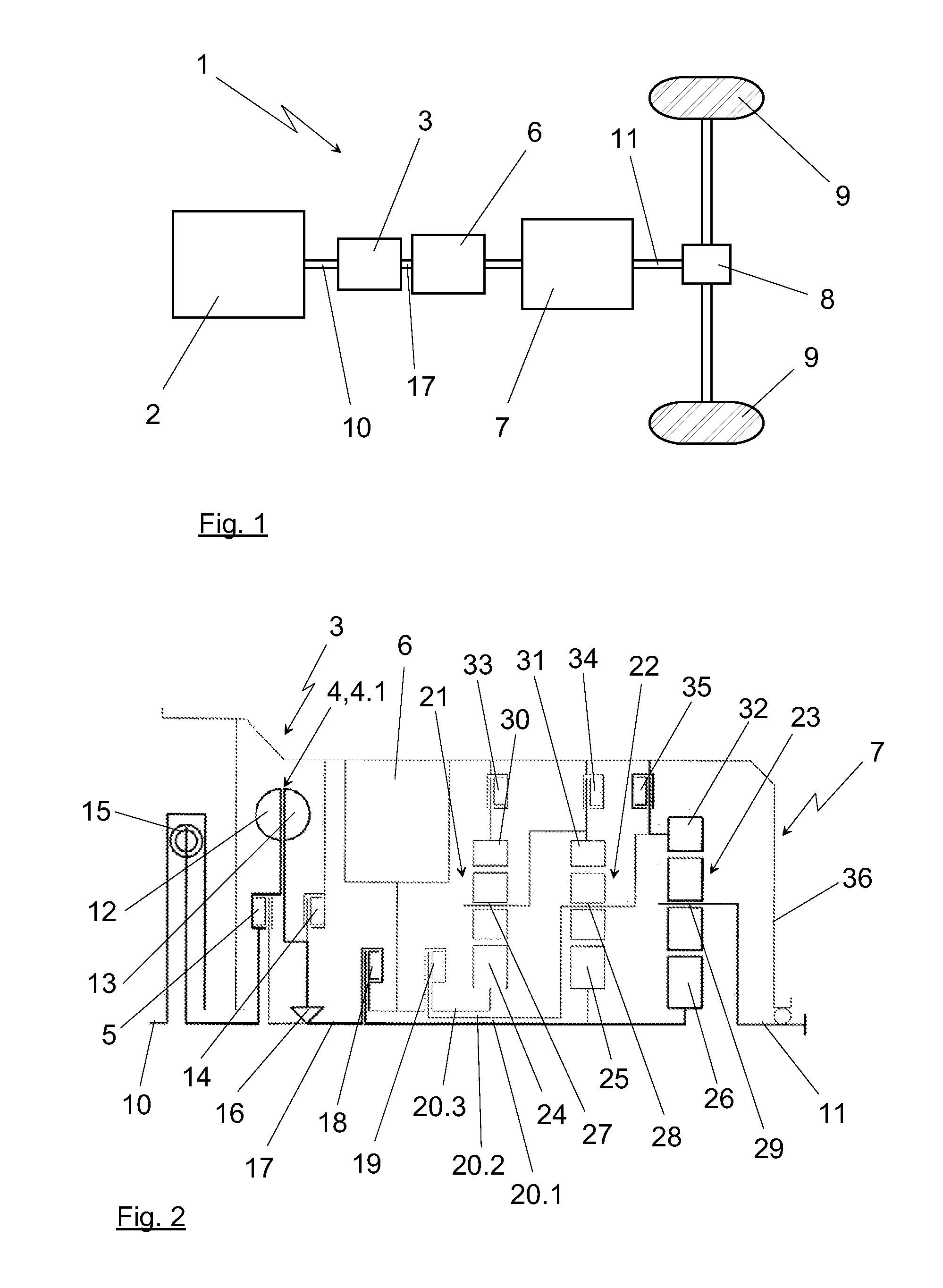
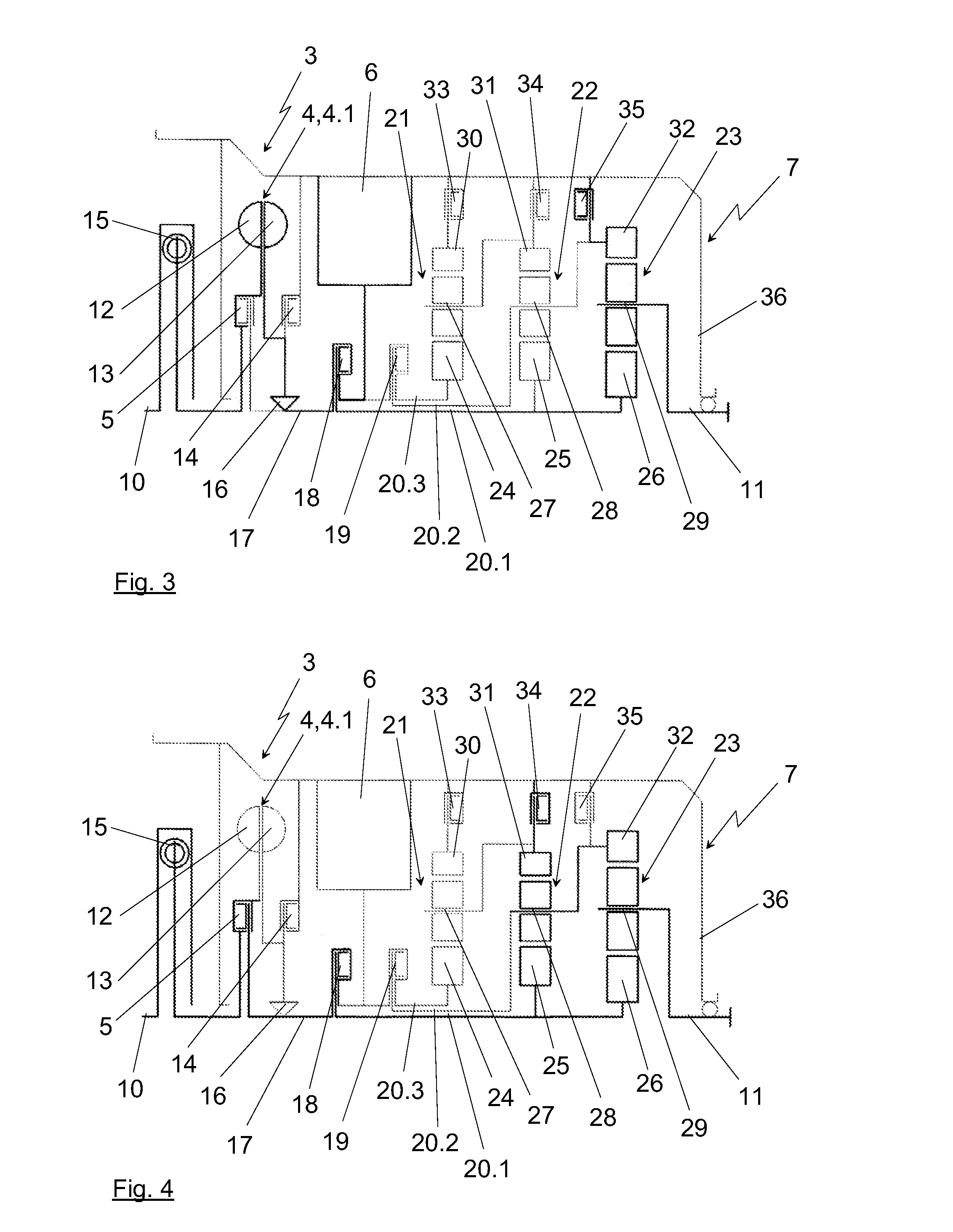
[0046]The illustrations of FIGS. 2 to 8 show an exemplary configuration of a section of such a drive train 1, with merely the portion of the rotationally symmetrical configuration disposed above the rotational axis being illustrated. FIGS. 2 to 8 show different shifting states of the configuration, which will be explained below and will explain the functionality of the configuration thereby.

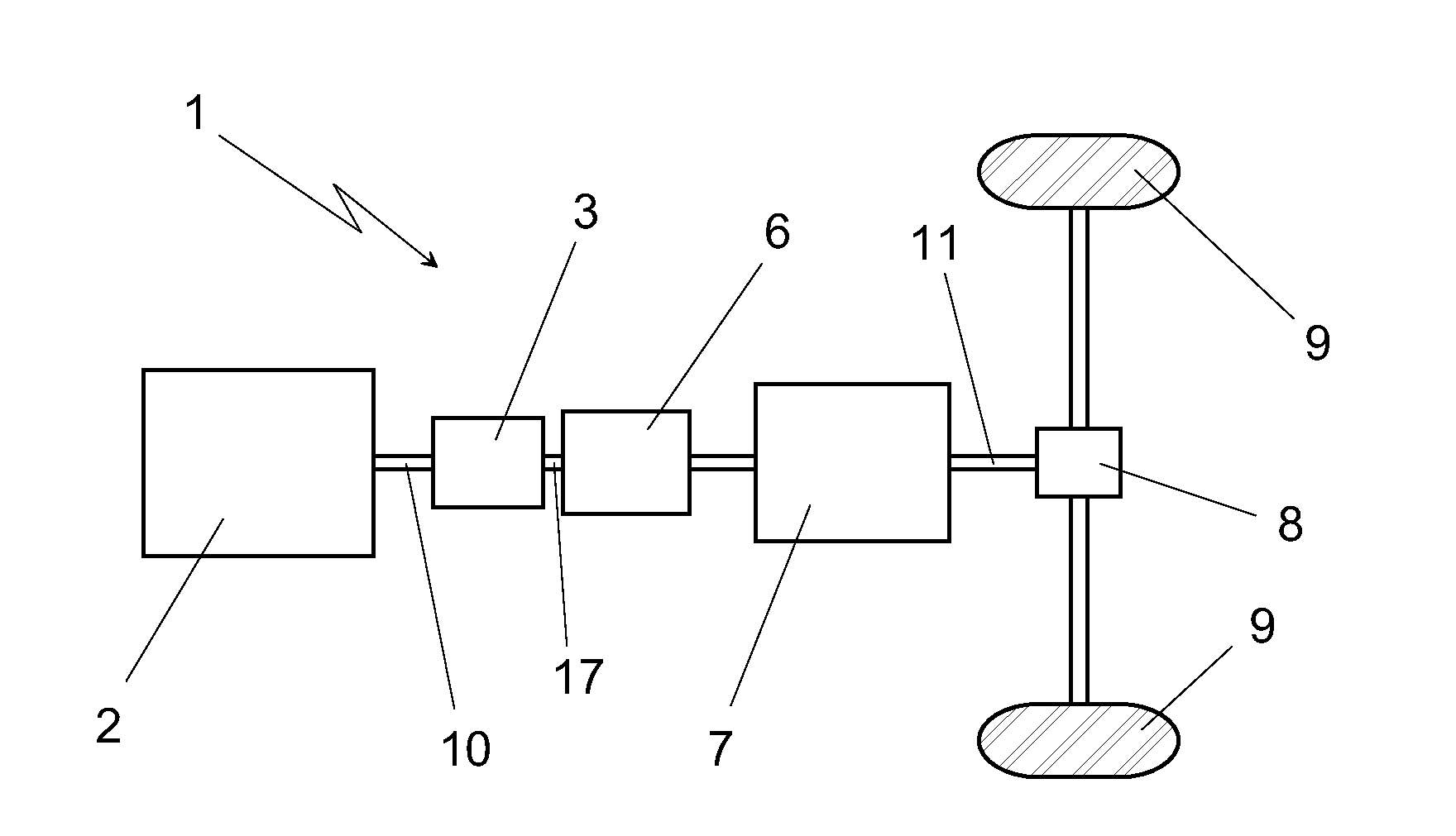
[0047]The illustration of FIG. 2 shows the starting element 3, the powershift transmission 7 and the interposed electrical machine 6. An input shaft 10 into the starting element 3 is shown in the illustration as chosen in FIG. 2 on the left. It is simultaneously the output shaft of the primary drive unit 2, or it is connected directly or indirectly with the same. The configuration as shown in FIG. 2 ends on the right side with output shaft 11 of the powershift transmission 7, which drives the drive wheels 9 directly or—as indicated in the illustration of FIG. 1—via a transfer gear 8. A hydrodynam...

second embodiment

[0057]The illustration of FIG. 9 shows the drive train 1 in a manner comparable with FIGS. 2 to 8. Since the different gear steps and driving states can be realized similar to those described in FIGS. 2 to 8, FIGS. 9 to 18 merely show the structures of the configurations of the various possible embodiments of the drive train 1 without the thickness of the lines symbolizing the power flow, as was the case in FIGS. 2 to 8.

[0058]In the configuration as shown in FIG. 9, the hydraulic element 4 is also arranged as a hydrodynamic coupling, which is arranged with a rotating housing and is provided as a hydrodynamic coupling 4.2 with constant filling. The hydrodynamic coupling 4.2 with constant filling shall be understood with respect to its functionality in such a way that it is always filled at a constant degree of filling. Since the lock-up clutch 5 is closed in non-operation of the hydrodynamic coupling 4.2 and the components therefore revolve with the same rotational speed, the continu...

eighth embodiment

[0066]The illustration in FIG. 16 describes the same configuration as in the eighth embodiment in the illustration of FIG. 15, with the housing of the hydrodynamic torque converter 4.4 being connected in a torque-proof manner with the housing 36 in this case and the freewheel 42 can therefore be omitted. The guide wheel 41 is also connected in this case in a torsion-proof way with the housing 36. The turbine or secondary side 13 is coupled via the freewheel 16 with the powershift transmission 7 in a manner that has already been described several times above. As a result of the housing of the hydrodynamic converter 4.4 which is connected in a torsion-proof manner with the housing 36, filling of the hydrodynamic converter 4.4 with working medium will only occur in the first gear and in the reverse gear, similar to the hydrodynamic coupling 4.2 with constant filling, in order to minimize the occurring ventilation losses in the area of the hydrodynamic converter 4.4 in the other gears. ...


PUM


Abstract

A drive train for a motor vehicle includes: a primary drive unit; a powershift transmission which is arranged behind the primary drive unit in the direction of the power flow; a starting element which is arranged in the power flow between the primary drive unit and the powershift transmission and which includes at least one coupling; an electrical machine which is arranged in the power flow between the starting element and the powershift transmission; and at least one retarder which is arranged in the power flow before and/or after the powershift transmission.

Description

CROSS REFERENCE TO RELATED APPLICATIONS [0001]This is a continuation of PCT application No. PCT / EP2011 / 000938, entitled “DRIVETRAIN FOR A MOTOR VEHICHLE”, filed Feb. 25, 2011, which is incorporated herein by reference.BACKGROUND OF THE INVENTION[0002]1. Field of the Invention[0003]The invention relates to a drive train for a motor vehicle, including: a primary drive unit; a powershift transmission which is arranged behind the primary drive unit in the direction of the power flow; a starting element which is arranged in the power flow between the primary drive unit and the powershift transmission and which comprises at least one coupling; an electrical machine which is arranged in the power flow between the starting element and the powershift transmission. In particular, the invention further relates to the use of such a drive train for a utility vehicle, preferably for a city bus, as can be used in urban transport for example.[0004]2. Description of the Related Art[0005]Hybridized d...

Claims


Application Information

Patent Timeline
IPC IPC(8): F02N7/00B60W10/196
CPCB60K6/38Y10T74/134B60K6/48B60K6/547B60W10/023B60W10/196B60W2300/10B60Y2200/143B60Y2400/4242F16H2041/246F16H2045/0284F16H2045/0289Y02T10/6221F02N7/00B60K6/383Y02T10/62
Inventor MEIER-BURKAMP, GERHARDKRIEGER, HELMUT
Owner VOITH PATENT GMBH
Why Eureka
Try Eureka