Solar cell

a solar cell and current conversion technology, applied in the field of solar cells, can solve the problem of low current conversion efficiency of solar cells, and achieve the effect of solar cell efficiency according to the situation

Inactive Publication Date: 2013-08-15
LG ELECTRONICS INC
View PDF12 Cites 16 Cited by
  • Summary
  • Abstract
  • Description
  • Claims
  • Application Information

AI Technical Summary

Benefits of technology

[0035]Thus, the efficiency of the solar cell according to the embodiment of the invention may further increase

Problems solved by technology

Because light is generally incident only on one surface of the substrate o

Method used


Image

  • Solar cell
  • Solar cell
  • Solar cell

Examples


first embodiment

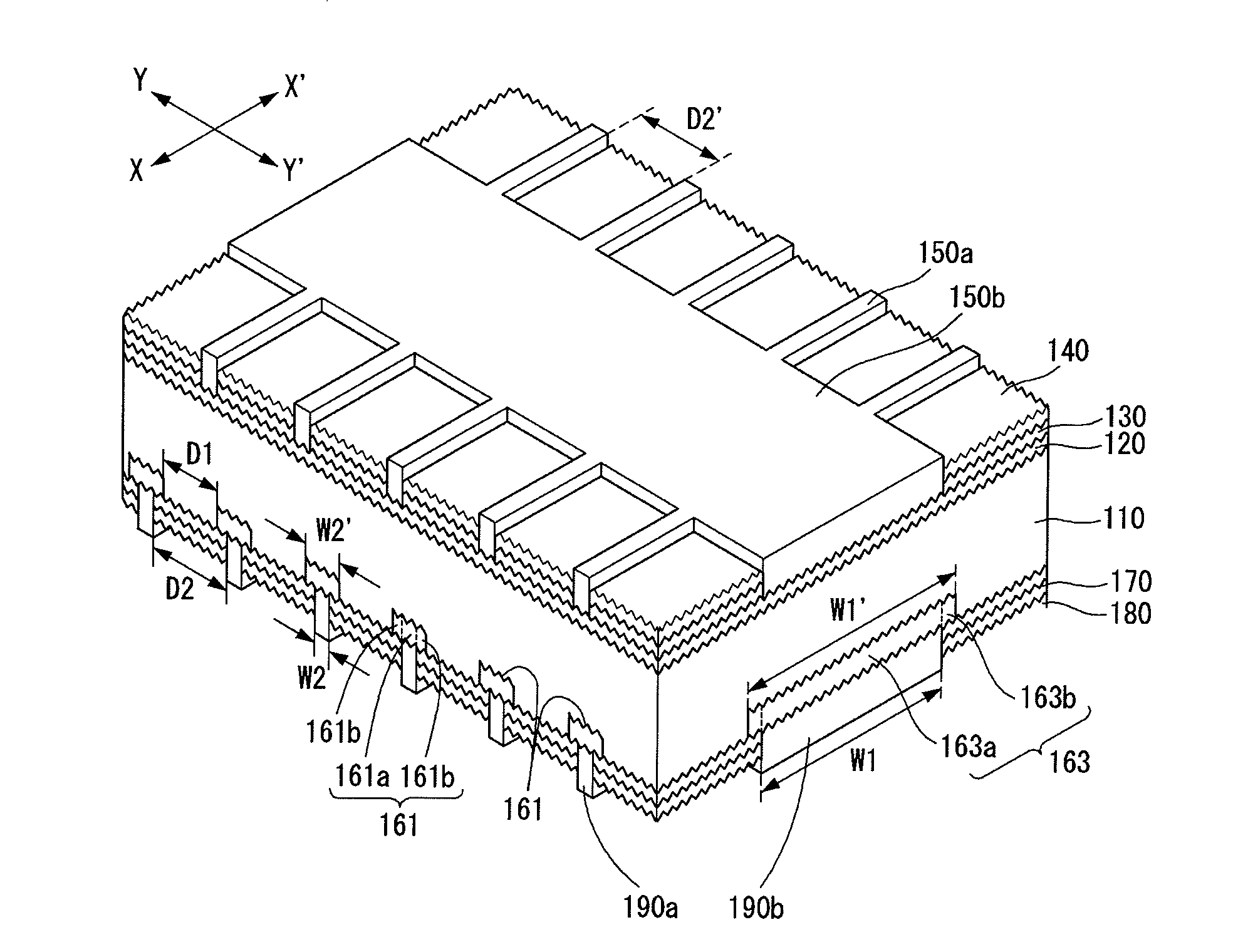
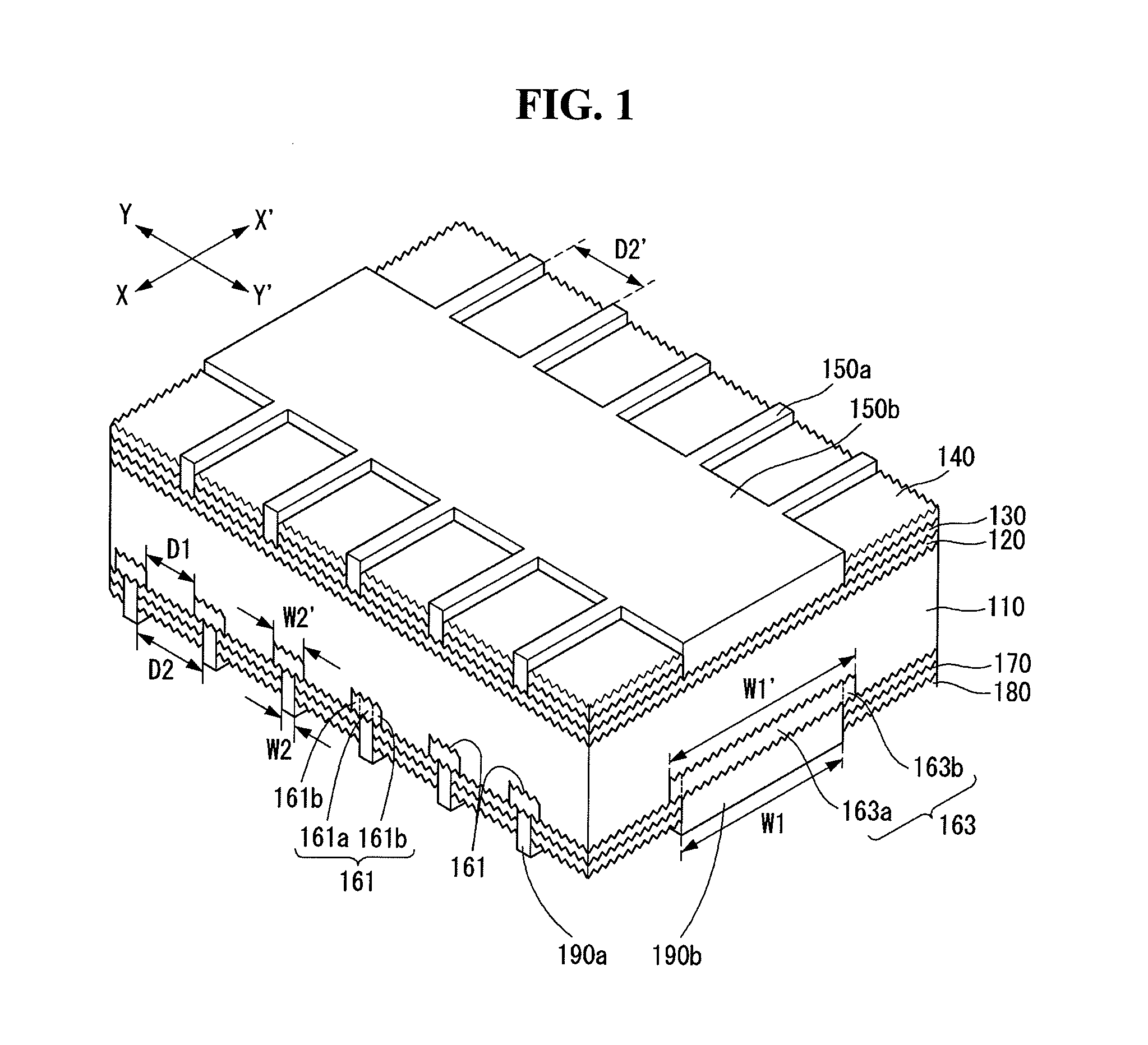
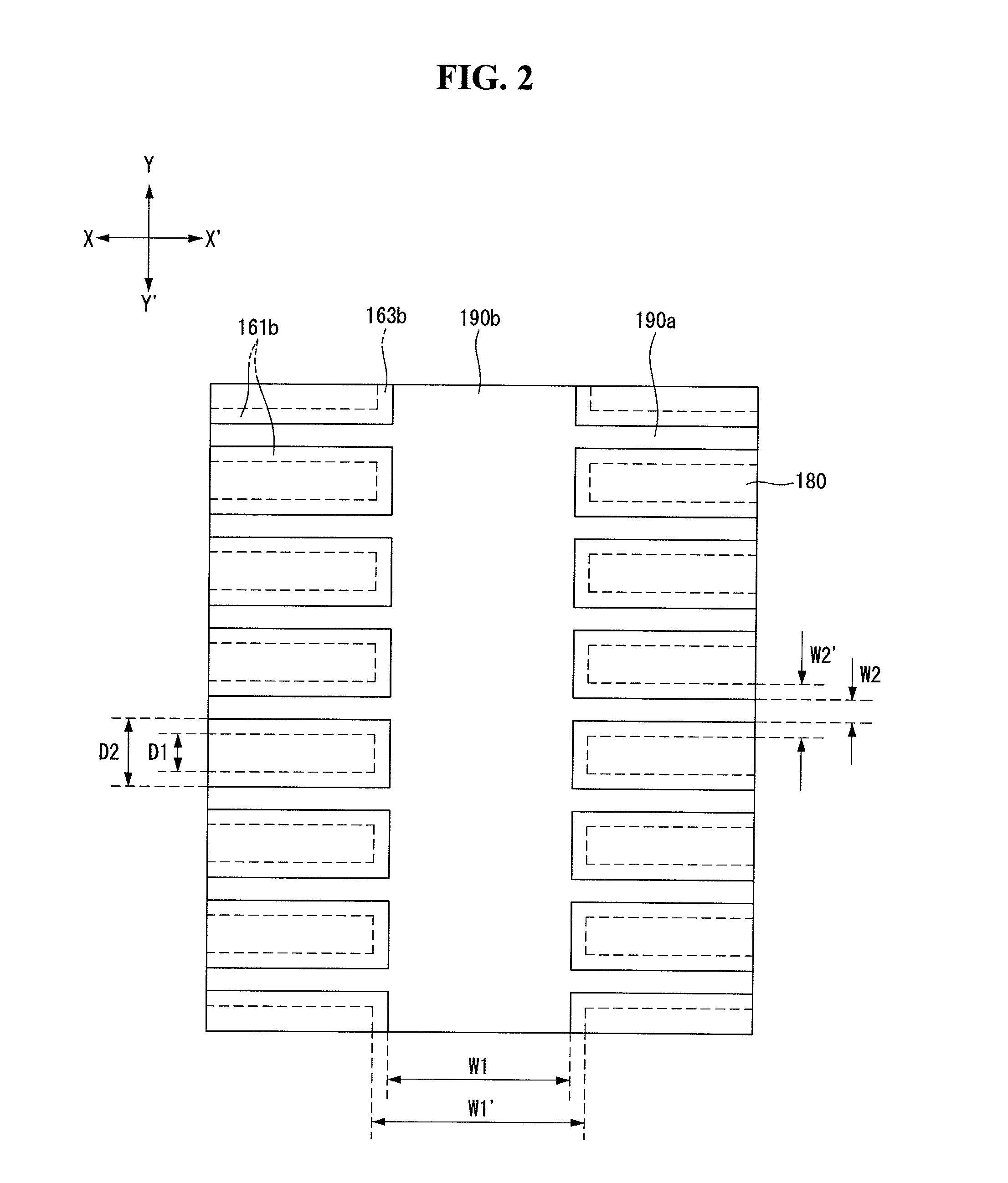
[0045]FIG. 1 is a schematic perspective view of a solar cell according to the invention. FIG. 2 is a plane view showing a back surface of the solar cell shown in FIG. 1.

[0046]As shown in FIG. 1, the solar cell according to the first embodiment of the invention includes a substrate 110, an emitter region 120 positioned at one surface of the substrate 110, for example, a front surface of the substrate 110, a first passivation layer 130 positioned on the emitter region 120, a first anti-reflection layer 140 positioned on the first passivation layer 130, a plurality of first electrodes 150a and a first current collector 150b positioned on the emitter region 120 on which the first passivation layer 130 and the first anti-reflection layer 140 are not positioned, a back surface field (BSF) region (shown as elements 161 and 162) positioned at a back surface of the substrate 110, a second passivation layer 170 positioned on the back surface of the substrate 110, a second anti-reflection laye...

second embodiment

[0104]A solar cell according to the invention is described below with reference to FIGS. 3 and 4.

[0105]Since configuration of the solar cell according to the second embodiment of the invention is substantially the same as the solar cell according to the first embodiment of the invention except an emitter region and a back surface field region, a further description may be briefly made or may be entirely omitted.

[0106]The emitter region 120 of the solar cell according to the first embodiment of the invention substantially has a uniform doping concentration throughout the entire front surface of the substrate 110. Thus, the emitter region 120 according to the first embodiment of the invention may be easily manufactured through a simple process, but a recombination rate of carriers may increase because of the high doping concentration of the emitter region 120. As a result, an improvement in the efficiency of the solar cell may be limited.

[0107]Accordingly, the solar cell according to ...


PUM


Abstract

A solar cell includes a substrate of a first conductive type, a plurality of first electrodes which are positioned on one surface of the substrate and extending in a first direction, an emitter region which is electrically connected to the first electrodes and is of a second conductive type opposite the first conductive type, a plurality of second electrodes which are positioned on another surface of the substrate and extending in the first direction, and a back surface field region including a plurality of first field regions which are locally formed at locations corresponding to the second electrodes in the same direction as the second electrodes and are electrically connected to the second electrodes. A distance between adjacent first field regions is less than a distance between adjacent second electrodes.

Description

[0001]This application claims priority to and the benefit of Korean Patent Application No. 10-2012-0014116 filed in the Korean Intellectual Property Office on Feb. 13, 2012, the entire contents of which are incorporated herein by reference.BACKGROUND OF THE INVENTION[0002]1. Field of the Invention[0003]Embodiments of the invention relate to a solar cell.[0004]2. Description of the Related Art[0005]Solar power generation to convert light energy into electric energy using a photoelectric conversion effect has been widely used as a method for obtaining eco-friendly energy. A solar power generation system using a plurality of solar cell modules has been installed in places, such as houses, due to an improvement of a photoelectric conversion efficiency of solar cells.[0006]A solar cell generally includes a substrate and an emitter region forming a p-n junction along with the substrate. The solar cell generates an electric current using light incident through one surface of the substrate....

Claims


Application Information

Patent Timeline
IPC IPC(8): H01L31/0224H01L31/0236H01L31/0232
CPCH01L31/02168H01L31/022441Y02E10/547H01L31/0684H01L31/0236H01L31/02363H01L31/042
Inventor HA, JUNGMINCHOE, YOUNGHOPARK, CHANGSEO
Owner LG ELECTRONICS INC
Why Eureka
Try Eureka