Moisture abatement in heating operation of climate controlled systems

a technology of climate control and heating operation, applied in the field of climate control, can solve the problems of occupant's back and other pressure points being sweaty, vehicle seats being very hot and uncomfortable for a long time, and problems that have been experienced with existing climate control systems, and achieve the effect of reducing temperatur

Active Publication Date: 2013-08-15
GENTHERM INC
View PDF36 Cites 58 Cited by
  • Summary
  • Abstract
  • Description
  • Claims
  • Application Information

AI Technical Summary

Benefits of technology

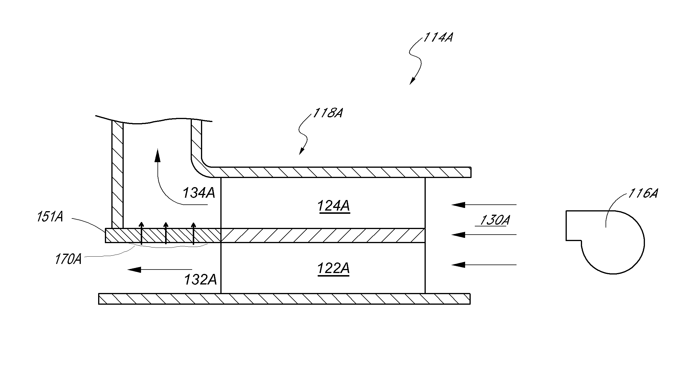
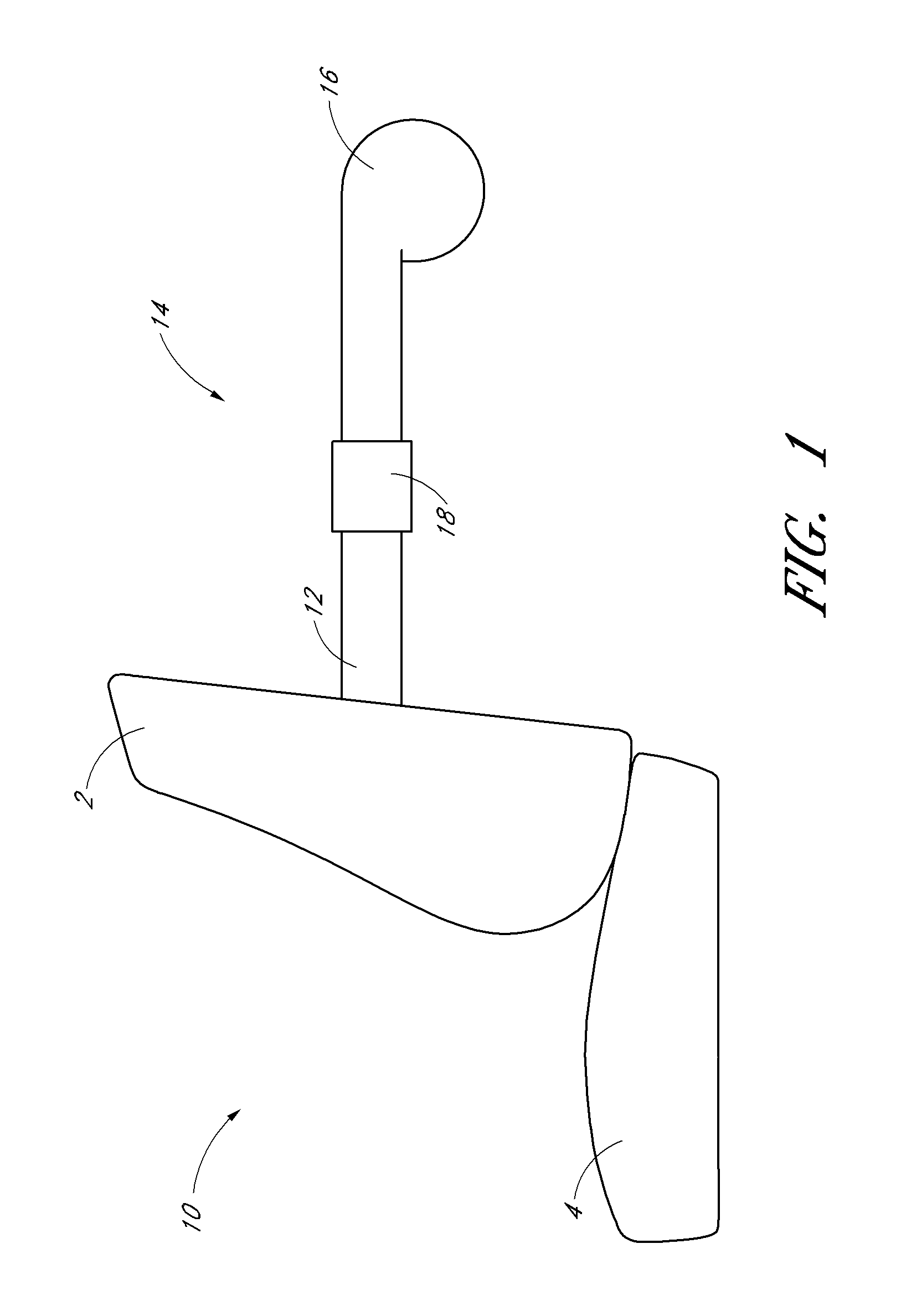
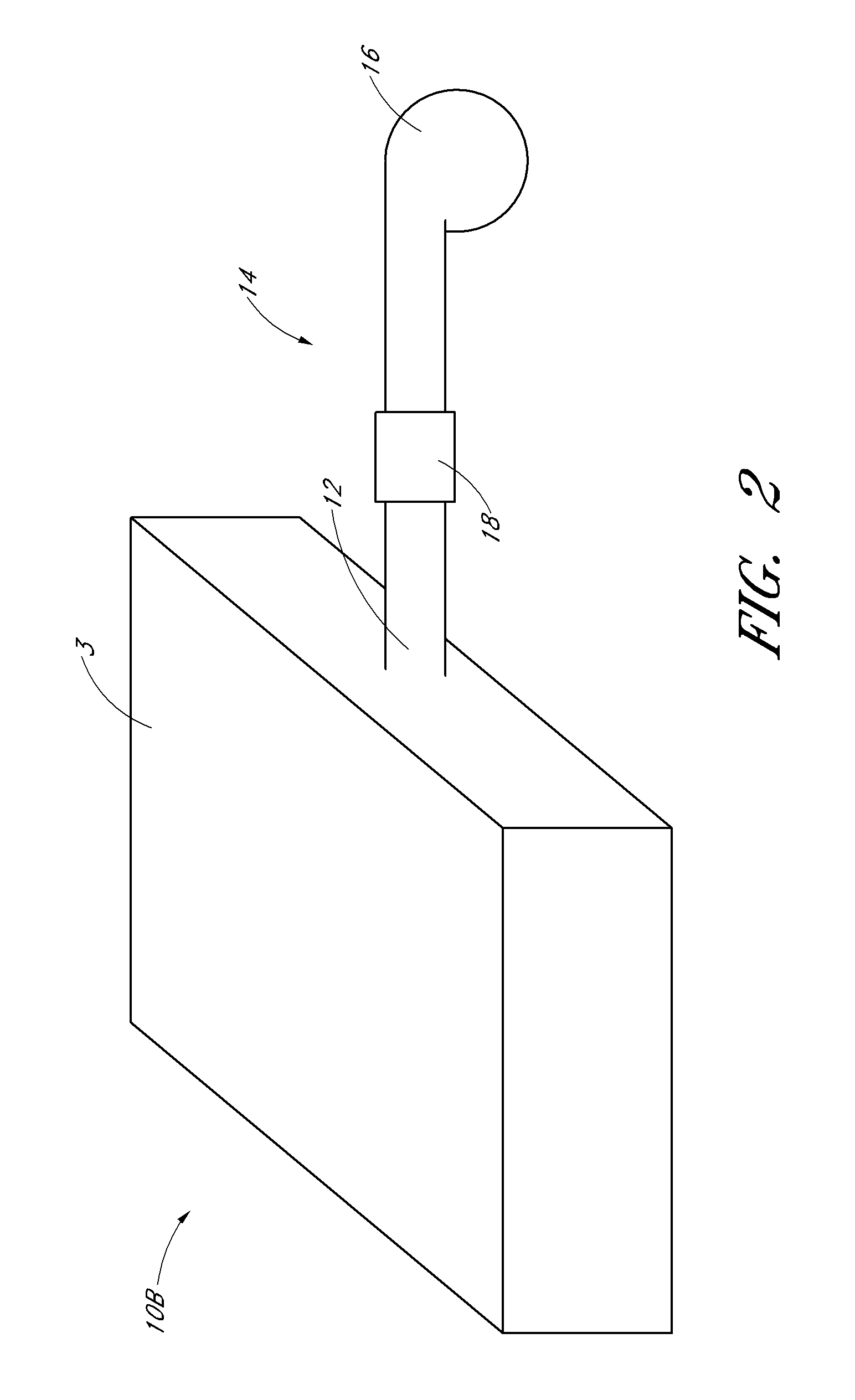
[0006]U.S. Pat. Nos. 8,104,295, 8,605,763, 7,927,805 and 7,963,594 (the entirety of these patents are hereby incorporated by reference herein in their entirety) disclose systems in which a thermoelectric (TE) device (TED) is used to heat and / or cool a bed, vehicle seat, a chair, and / or a cup holder or container. When running the TED in heating mode, the waste side of the TED can achieve temperatures below that of the main side and, if humidity levels are sufficient, condensate can form on the heat exchanger. The formation of the water droplets can restrict the airflow across the heat exchanger and cause a further reduction in temperature due to reduced airflow. If the TED temperature levels fall below 0° C., ice formation begins, further restricting or even preventing air flow across the waste side of the heat exchanger.

Problems solved by technology

For example, an automotive vehicle exposed to the summer weather, especially where the vehicle has been parked in an unshaded area for a long period of time, can cause the vehicle seat to be very hot and uncomfortable for the occupant for some time after entering and using the vehicle, even with normal air conditioning.
Furthermore, even with normal air-conditioning, on a hot day, occupant's back and other pressure points may remain sweaty while seated.
This is particularly true where a typical vehicle heater is unlikely to quickly warm the vehicle's interior.
There are, however, problems that have been experienced with existing climate control systems.
This condensation often can have undesirable consequences, from corrosion on metal parts to the creation of mold.
Condensation may also partially or totally block airflow at the fin passages on the main side of the TED, resulting in reduction or loss of function.

Method used


Image

  • Moisture abatement in heating operation of climate controlled systems
  • Moisture abatement in heating operation of climate controlled systems
  • Moisture abatement in heating operation of climate controlled systems

Examples


Embodiment Construction

[0043]A variety of examples described below illustrate various configurations that may be employed to achieve desired improvements. The particular embodiments and examples are only illustrative and not intended in any way to restrict the general inventions presented and the various aspects and features of these inventions. In addition, it should be understood that the terms cooling side, heating side, main side, waste side, cooler side and hotter side and the like do not indicate any particular temperature, but are relative terms. For example, the “hot,”“heating” or “hotter” side of a thermoelectric device or array may be at ambient temperature, with the “cold,”“cooling” or “cooler” side at a cooler temperature than ambient. Conversely, the “cold,”“cooling” or “cooler” side may be at ambient with the “hot,”“heating” or “hotter” side at a higher temperature than ambient. Thus, the terms are relative to each other to indicate that one side of the thermoelectric device is at a higher o...


PUM


Abstract

Embodiments related to moisture abatement during a heating operation of a climate control system are disclosed. In some embodiments, the climate control system includes a thermoelectric device (TED) or other thermal condition device having a hot side and a cold side. In certain embodiments, the thermal conditioning device is operated (e.g., by a processor or a condensate switch) to inhibit or prevent the occurrence of condensation, and/or to abate condensation that has already occurred, on the cold side of the thermal conditioning device during the heating operation.

Description

CROSS REFERENCE TO RELATED APPLICATIONS[0001]This application claims the priority benefit under 35 U.S.C. §119(e) of U.S. Provisional Application No. 61 / 597,568, filed Feb. 10, 2012, the entirety of which is hereby incorporated by reference.FIELD OF THE INVENTIONS[0002]This application relates generally to climate control, and more specifically, to climate control utilizing a thermoelectric circuit.DESCRIPTION OF THE RELATED ART[0003]Temperature modified air for environmental control of living or working space is typically provided to relatively extensive areas, such as entire buildings, selected offices, or suites of rooms within a building. In the case of vehicles, such as automobiles, the entire vehicle is typically cooled or heated as a unit. There are many situations, however, in which more selective or restrictive air temperature modification is desirable. For example, it is often desirable to provide individualized climate control for an occupant seat so that substantially in...

Claims


Application Information

Patent Timeline
Patent Type & Authority Applications(United States)
IPC IPC(8): F24D19/10
CPCF24D19/1096F24H3/0429F24H9/2064B60H1/00478F24F2221/10F24F5/0042H05B1/0238H05B1/0283B60H1/3233B60N2/5635B60N2/5657B60N2/5692
Inventor BRYKALSKI, MICHAELMARQUETTE, DAVID
Owner GENTHERM INC
Why Eureka
Try Eureka