
System, apparatus and method for long endurance vertical takeoff and landing vehicle

a technology of vertical takeoff and landing vehicle and long endurance, which is applied in vertical landing/takeoff aircraft, automatic actuation, transportation and packaging, etc., can solve the problems of requiring long endurance in the new competitive landscape of vtol vehicles, and hampered attempts to develop organically deployable, etc., and achieves high aspect ratio and/or a payload

Inactive Publication Date: 2013-08-15
AURORA FLIGHT SCI CORP
View PDF1 Cites 92 Cited by
  • Summary
  • Abstract
  • Description
  • Claims
  • Application Information

AI Technical Summary

Benefits of technology

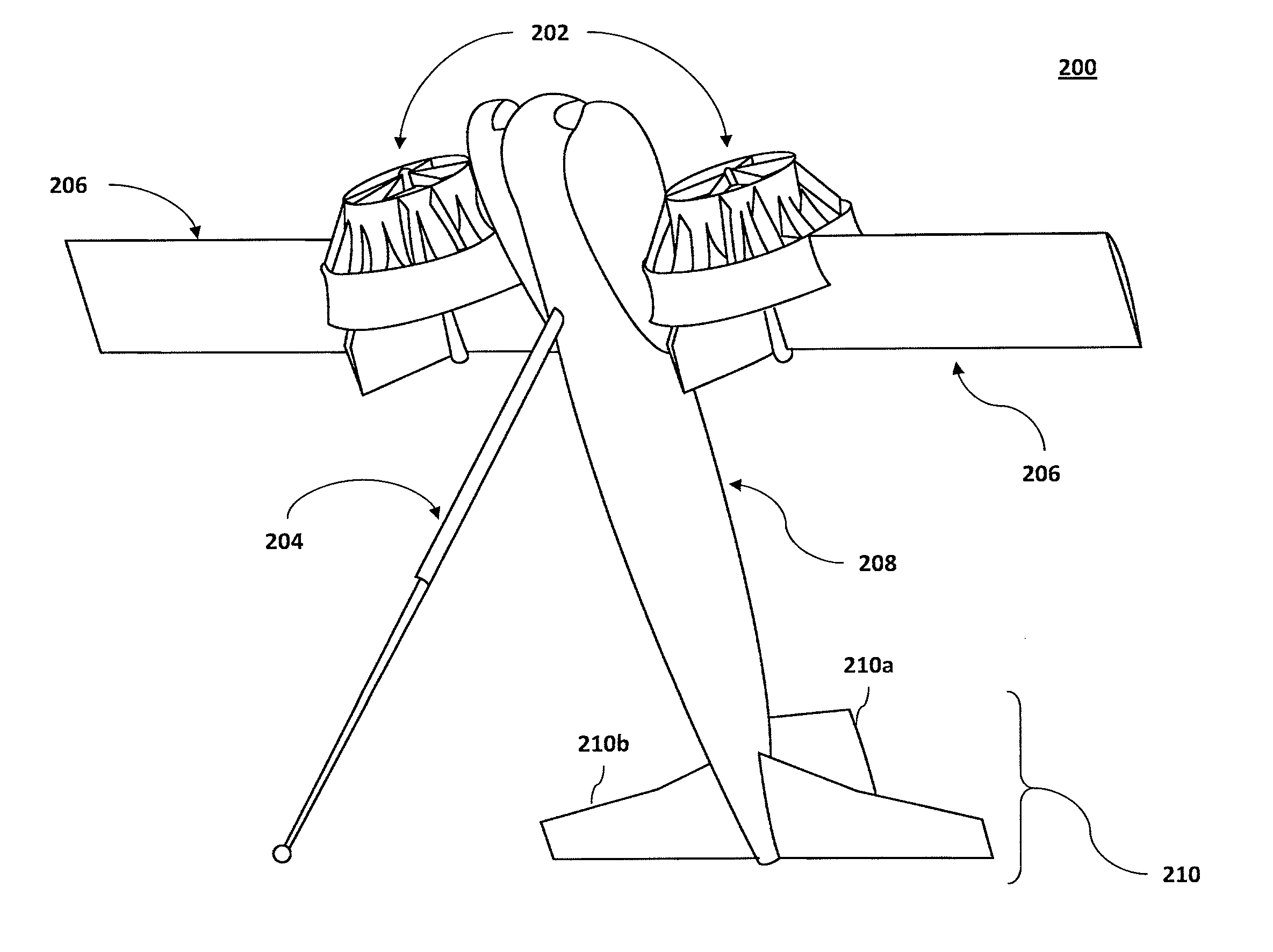
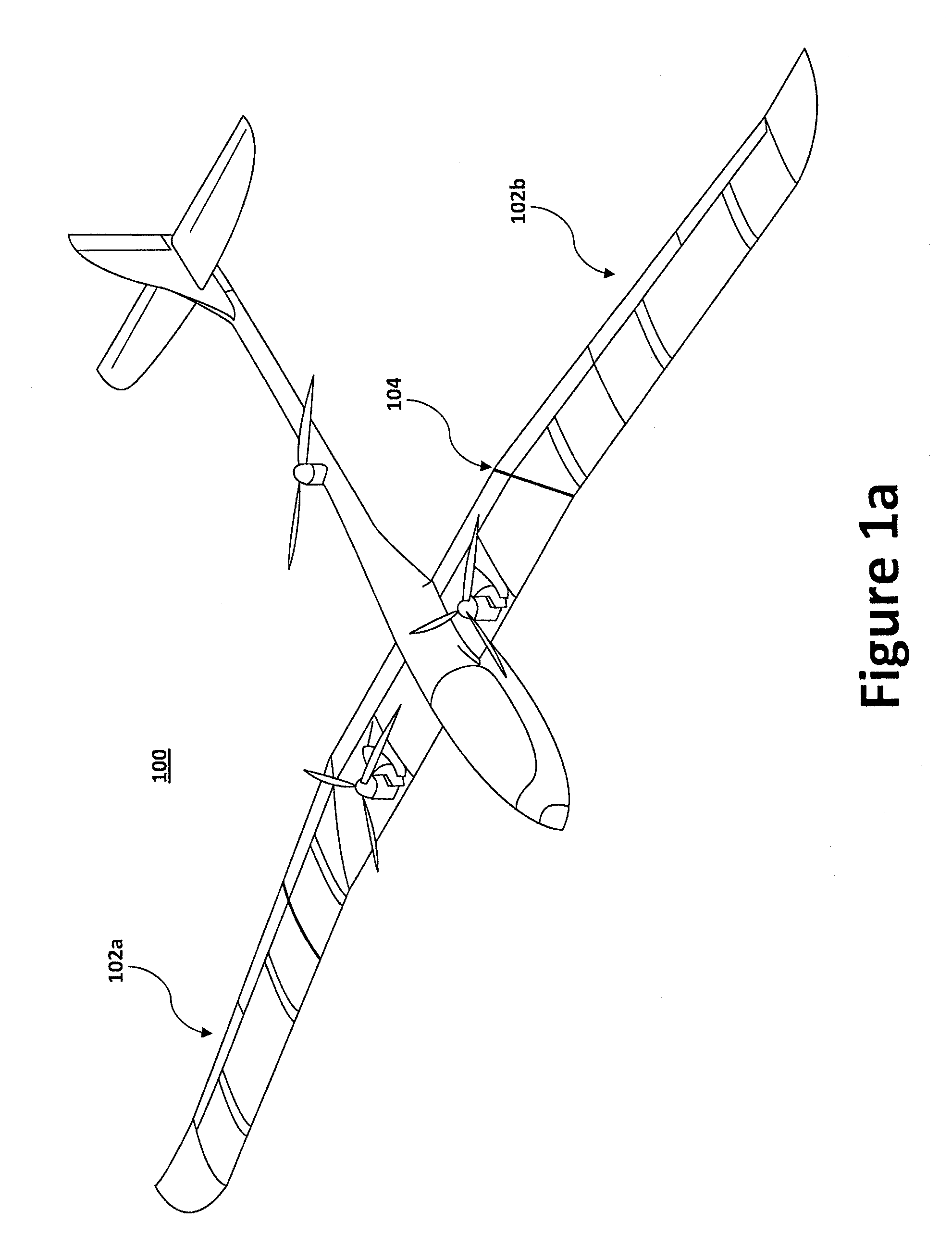
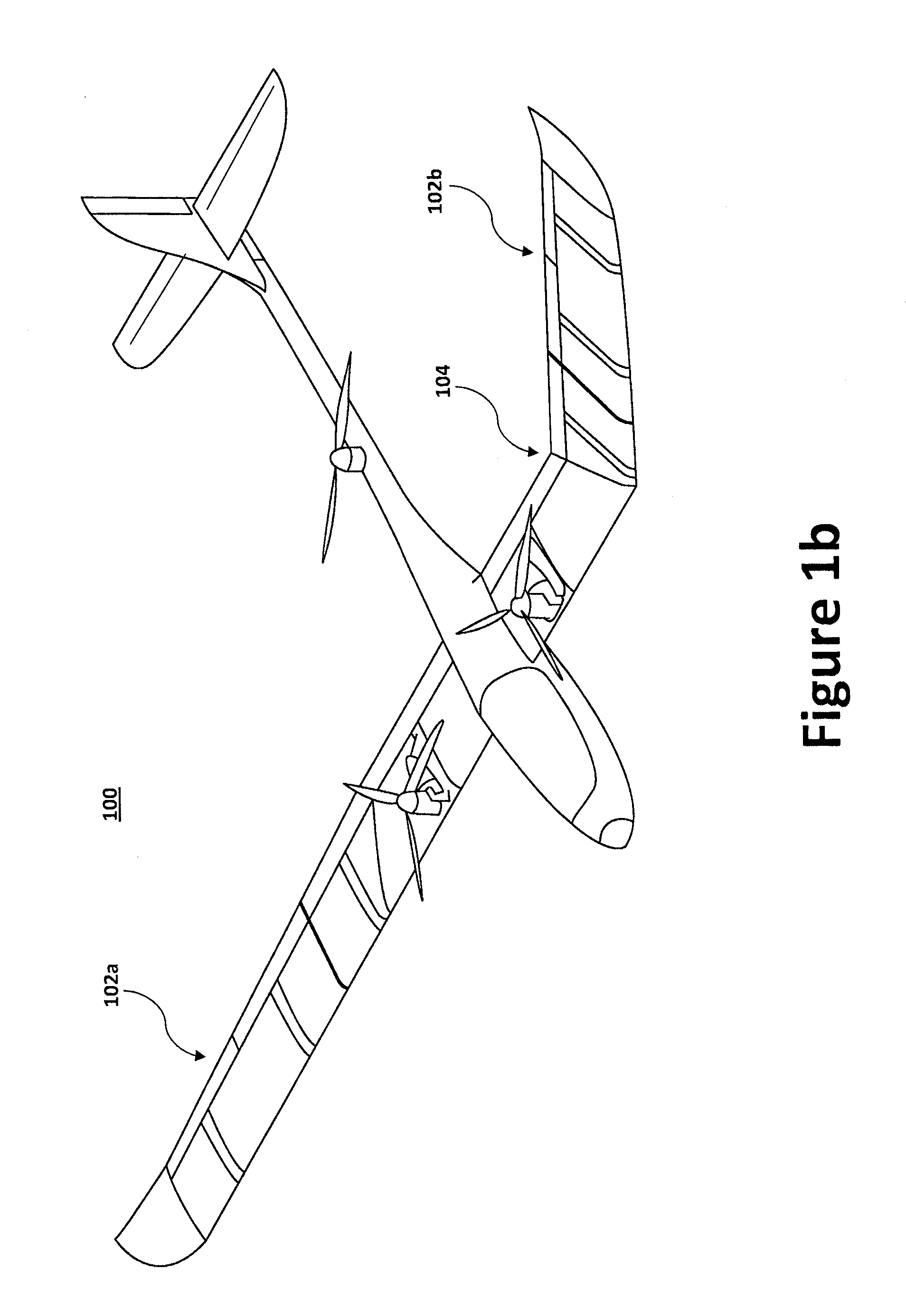
The present invention provides a system, method, and apparatus for organic deployment and operation of long-endurance, high-aspect ratio VTOL UAVs from confined spaces. The aircraft has a fuselage, empennage, counter-rotating engines, wing, and retractable pogo support. The wing can transform between a vertical and horizontal configuration using pivotal connectors on the fuselage. The aircraft can takeoff and land vertically, transition to wingborne flight, and achieve a predetermined stand-up angle for takeoff and recovery. The aircraft may have a high aspect ratio and payload for intelligence, surveillance, and reconnaissance. The technical effects of the invention include improved efficiency, flexibility, and reduced risk of damage to the aircraft.

Problems solved by technology

Until recently, however, the efficiency penalty associated with incorporating a hover phase of flight, the complexity associated with transition from vertical to horizontal flight, and the necessity to reduce or eliminate exposure of ground personnel to exposed high-speed rotors have hindered attempts to develop organically deployable VTOL UAVs, which are expected to be very important assets.
Furthermore, the new competitive landscape for VTOL vehicles now requires long endurance, which can require flights in excess of 8 hours.

Method used


Image

  • System, apparatus and method for long endurance vertical takeoff and landing vehicle
  • System, apparatus and method for long endurance vertical takeoff and landing vehicle
  • System, apparatus and method for long endurance vertical takeoff and landing vehicle

Examples


Embodiment Construction

[0030]Embodiments of the present invention will be described hereinbelow with reference to the accompanying drawings. In the following description, well-known functions or constructions are not described in detail because they would obscure the invention in unnecessary detail. The present disclosure endeavors to provide a system, method and apparatus that allows organic deployment and operation of long-endurance, high aspect ratio VTOL UAVs from confined spaces.

[0031]An objective of the present application is to provide a tier 2-sized long-endurance Robust Efficient Vertical Launch and Recovery (REVLAR) UAV, a form of VTOL UAV. Additionally, the present application shall illustrate how a design may be scaled and shall identify exemplary size, weight, and endurance limits for a REVLAR UAV. Particular attention shall be paid to control strategies, especially in the VTOL mode, and associated transition to long-endurance flight. While the techniques and subject matter of the present dis...


PUM


Abstract

A vertical take-off and landing (VTOL) aircraft according to an aspect of the present invention comprises a fuselage, an empennage having an all-moving horizontal stabilizer located at a tail end of the fuselage, a wing having the fuselage positioned approximately halfway between the distal ends of the wing, wherein the wing is configured to transform between a substantially straight wing configuration and a canted wing configuration using a canted hinge located on each side of the fuselage. The VTOL aircraft may further includes one or more retractable pogo supports, wherein a retractable pogo support is configured to deploy from each of the wing's distal ends.

Description

TECHNICAL FIELD[0001]The present invention relates to system and methods for vertical takeoff and landing of a long-endurance Unmanned Aerial Vehicle (“UAV”). More specifically, the present invention relates to systems and methods for vertical takeoff and landing of long-endurance Tier 2 UAVs.BACKGROUND INFORMATION[0002]There has long been a need, exacerbated by today's overseas contingency operations, for vertical take-off and landing (“VTOL”) vehicles that are capable of being deployed from confined spaces. In fact, many situations favor vehicles, specifically UAVs, that can launch and recover vertically without requiring complex or heavy ground support equipment. The ability to organically deploy a UAV is particularly attractive in situations such as forward-operating bases, clandestine locales, payload emplacement, and on-the-move situations. Until recently, however, the efficiency penalty associated with incorporating a hover phase of flight, the complexity associated with tran...

Claims


Application Information

Patent Timeline
Patent Type & Authority Applications(United States)
IPC IPC(8): B64C29/00
CPCB64C2201/187B64D43/00B64C2201/021B64C2201/088B64C2201/102B64C2201/108B64C2201/162B64C3/42B64D27/02B64C29/0091B64C29/00B64C25/10B64C9/00B64C5/02B64C29/0033B64U30/12B64U50/14B64U70/60B64U30/297B64U10/20B64U30/26B64U30/295B64C29/04B64C27/52B64C29/02B64C13/16
Inventor PADUANO, JAMES DONALDDAHLSTRAND, PAUL NILSWISSLER, JOHN BROOKE
Owner AURORA FLIGHT SCI CORP
Learn More