

Electrical power terminal
- Summary
- Abstract
- Description
- Claims
- Application Information
AI Technical Summary
Benefits of technology
Problems solved by technology
Method used
Image

Examples
Embodiment Construction
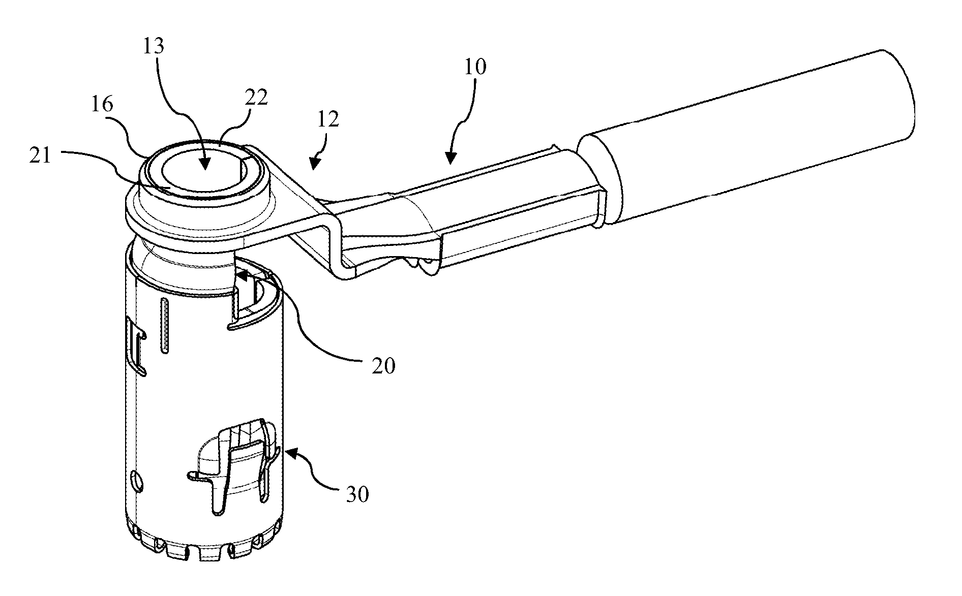
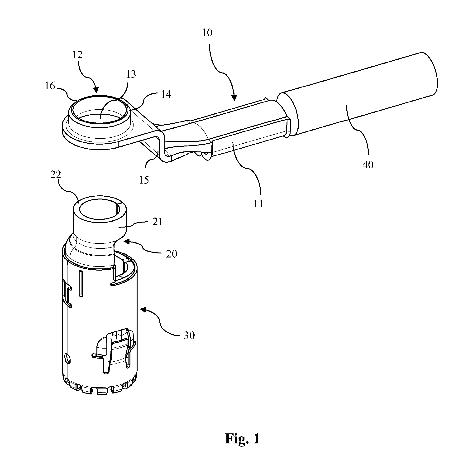
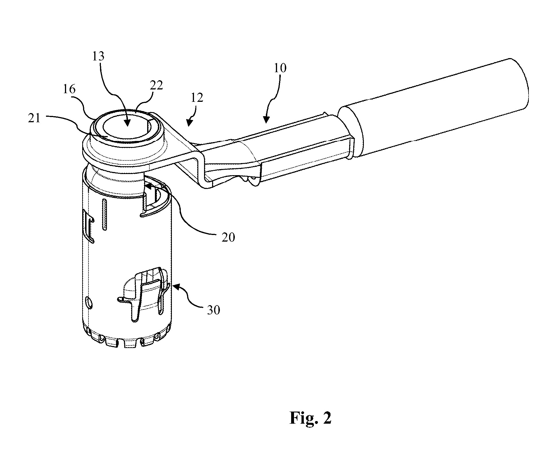
[0020]FIG. 1 is a schematic illustration of an exemplary electrical 90° (orthogonal) power terminal in accordance with the invention. The power terminal comprises an elongated wire connection member 10 as well as a terminal element 20. The wire connection member 10 is made from a stamped and bent piece of sheet metal (copper, aluminum, metal alloy, etc.) and is provided with a wire fastening portion 11 on one end and a terminal fastening portion 12 onto the terminal element 20, on the opposite end thereof. In the figures, a power line cable 40 is schematically shown, which is attached to the wire fastening portion 11 by means of a crimping or welding operation. The terminal fastening portion 12 comprises a circular opening 13 which is adapted to receive a connecting end 21 of the terminal element 20. The circular opening 13 is surrounded by a collar 14 which is of essentially cylindrical shape and projects upwardly from the plane of the circular opening 13 as one can see from FIG. 1...
PUM
 Abstract
Description
Claims
Application Information