Cutter chatter monitoring method

a monitoring method and cutter technology, applied in the field of monitoring methods, can solve the problems of affecting the life of cutters and machines, affecting the accuracy of cutting, and affecting the stability of the whole cutting process, so as to improve the efficiency and reliability of diagnosing abnormal cutting, increase the rotating speed of the main shaft, and enhance the effect of manufacturing precision

Inactive Publication Date: 2013-08-15
CHUNG YUAN CHRISTIAN UNIVERSITY
View PDF4 Cites 14 Cited by
  • Summary
  • Abstract
  • Description
  • Claims
  • Application Information

AI Technical Summary

Benefits of technology

[0006]In view of the problems of the prior art, it is a primary objective of the present invention to provide a cutter chatter monitoring method capable of monitoring cutters timely, and increasing a main shaft rotating speed when the cutters produce chatters to retard or avoid the continuous occurrence of cutter chatters, so as to enhance the manufacturing precision, yield rate and optimization. In addition, the invention avoids using the complicated signal transform analysis, and adopts the signal variation analysis and fast Fourier transform for analyzing signals and setting the diagnostic algorithm of the cutter chatters to improve efficiency and reliability of diagnosing abnormal cutting.

Problems solved by technology

Although present existing high-speed cutting can improve the material removal rate (MRR) by tens of times, yet the whole cutting process may become unstable and produce chatters.
As a result, the cutting precision, manufacturing surface roughness, and even the life of cutters and machines are affected adversely.
Although many conventional methods are available to avoid cutter chatters, these methods usually adopt a wavelet transform signal analysis with the disadvantages of a complicated computation, a low speed, and a poor effect, and these methods often fail to correct the cutter chatters timely.

Method used


Image

  • Cutter chatter monitoring method
  • Cutter chatter monitoring method
  • Cutter chatter monitoring method

Examples


Embodiment Construction

[0020]The technical contents of the present invention will become apparent with the detailed description of preferred embodiments and the illustration of related drawings as follows.

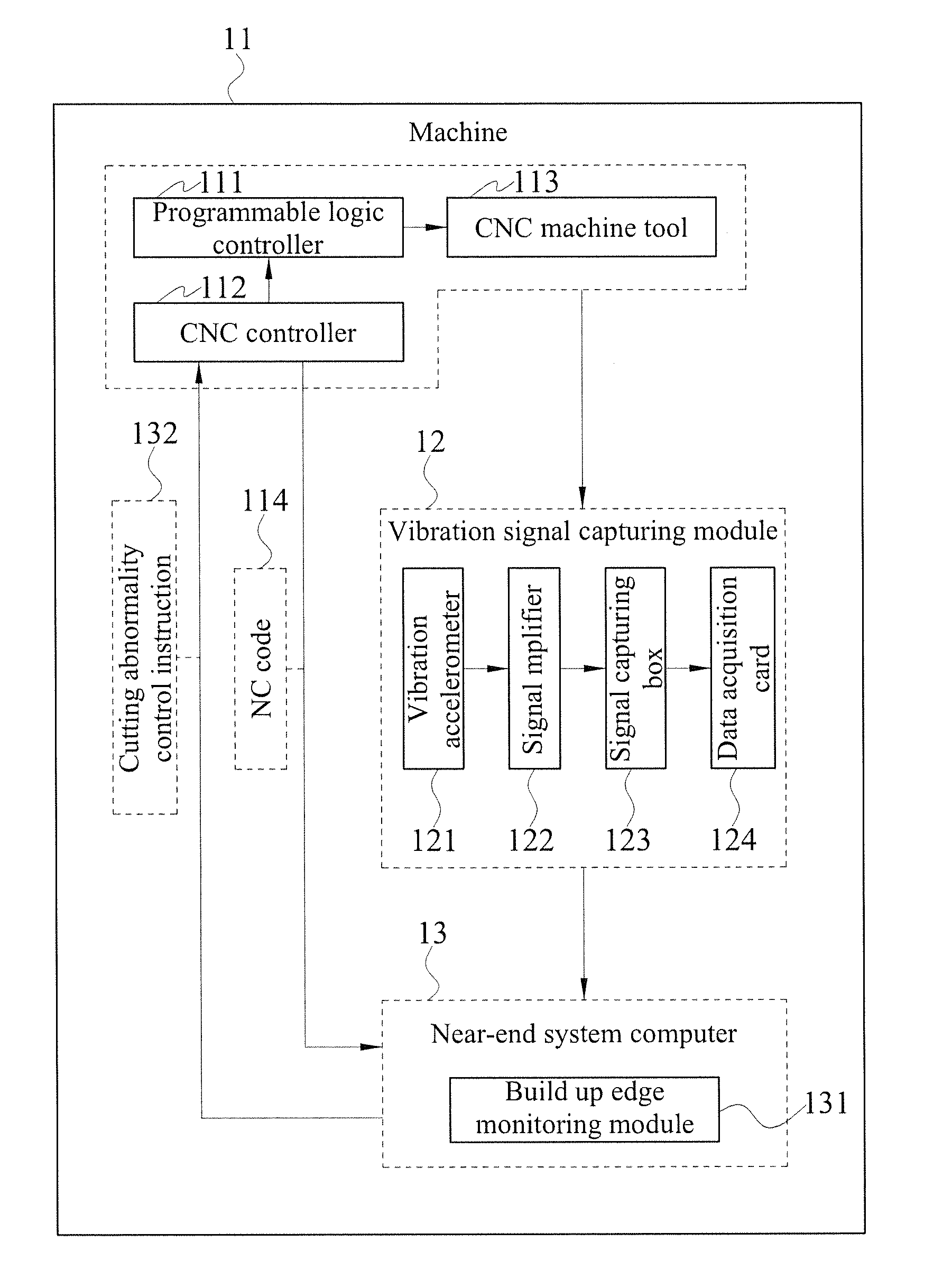
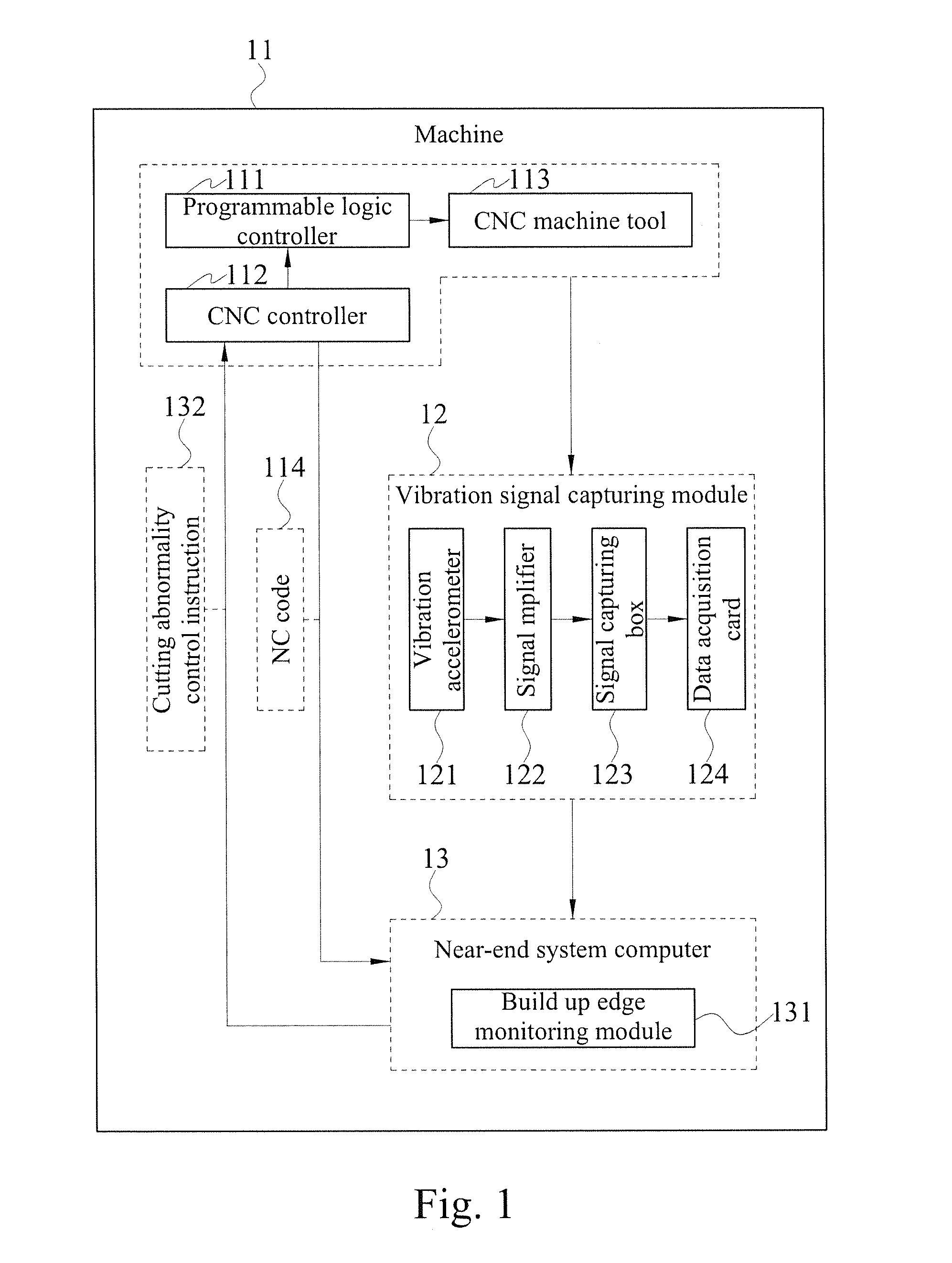
[0021]With reference to FIG. 1 for a system block diagram corresponding to a cutter chatter monitoring method in accordance a preferred embodiment of the present invention, a system using the cutter chatter monitoring method includes a machine 11, a vibration signal capturing module 12 and a near-end system computer 13.

[0022]The machine 11 comprises a programmable logic controller (PLC) 111, a computer numerical control (CNC) controller 112 and a CNC machine tool 113.

[0023]The vibration signal capturing module 12 comprises a vibration accelerometer 121, a signal amplifier 122, a signal capturing box 123 and a data acquisition card 124 (DAQ).

[0024]The near-end system computer 13 comprises a cutter chatter monitoring module 131.

[0025]When the machine starts the cutting, the system retrieves a cutting vibra...


PUM


Abstract

A cutter chatter monitoring method comprises the steps of capturing a cutting vibration acceleration signal; dividing the cutting vibration acceleration signal in each predetermined time period into a plurality of segments; determining whether the vibration acceleration signal of each segment is increased by a multiple greater than a threshold value; performing a Fast Fourier Transform of the cutting vibration acceleration signal in each predetermined time period; calculating a vibration frequency; determining whether the vibration frequency of the cutting vibration acceleration signal is a multiple of a cutter passing frequency; and increasing a main shaft rotating speed of a cutter to avoid cutter chatters if both aforementioned conditions are satisfied.

Description

BACKGROUND OF THE INVENTION[0001]1. Field of the Invention[0002]The present invention relates to a monitoring method, in particular to a cutter chatter monitoring method.[0003]2. Description of the Related Art[0004]Cutter chatter is generally caused by self-excited vibrations and considered as an unstable cutting phenomenon, and cutter charters are mainly divided into regenerative chatters, mode coupling chatters), and friction chatters. Among these charters, the regenerative chatter is the most common one. Although present existing high-speed cutting can improve the material removal rate (MRR) by tens of times, yet the whole cutting process may become unstable and produce chatters. As a result, the cutting precision, manufacturing surface roughness, and even the life of cutters and machines are affected adversely. Therefore, it is necessary to maximize the cutting performance of the high-efficiency machine, while suppressing the occurrence of chatters effectively, and it is an impo...

Claims


Application Information

Patent Timeline
Patent Type & Authority Applications(United States)
IPC IPC(8): G06F19/00
CPCB23Q17/0976G05B23/0235
Inventor WANG, SHIH-MINGHO, CHIEN-DA
Owner CHUNG YUAN CHRISTIAN UNIVERSITY
Why Eureka
Try Eureka