Apparatus for and a method of characterising mechanical properties of a sample

a technology of mechanical properties and apparatus, applied in the direction of instruments, fluid tightness measurement, structural/machine measurement, etc., can solve the problems of limited range of pressures at which the apparatus can operate, many uncertainties, and limited attempts, so as to reduce the frequency of the apparatus

Active Publication Date: 2013-08-22
CURTAIN UNIV OF TECH
View PDF4 Cites 29 Cited by
  • Summary
  • Abstract
  • Description
  • Claims
  • Application Information

AI Technical Summary

Benefits of technology

[0012]Having the pressure applicator arranged to apply a pressure to the sample in a second direction that is transversal to the first direction provides the significant advantage of allowing the first and second pressures to be controlled independently. In particular, such an arrangement allows the apparatus to simulate anisotropic stress conditions that would be experienced in typical subsurface locations.
[0015]The apparatus typically has a mass that is selected such that the resonance frequency of the apparatus is 0.1 Hz or less. Having a resonance frequency that is 0.1 Hz or less provides the significant advantage of allowing providing an extended frequency range of measurement, such as from 0 Hz to approximately 20 Hz.
[0022]In the above embodiments, the piston or pistons may be damped so as to further reduce the resonance frequency of the apparatus.
[0024]Resonant vibrations of the apparatus may be reduced by arranging the apparatus on a vibration damper.

Problems solved by technology

However, such corrections introduce many uncertainties.
So far, such attempts have been limited by technical constraints.
One disadvantage of this device is the limited range of pressures at which it can operate.
A further disadvantage arises from the resonance frequency of the measurement apparatus.
An additional practical disadvantage is that the sample can only be relatively small.

Method used


Image

  • Apparatus for and a method of characterising mechanical properties of a sample
  • Apparatus for and a method of characterising mechanical properties of a sample
  • Apparatus for and a method of characterising mechanical properties of a sample

Examples


Embodiment Construction

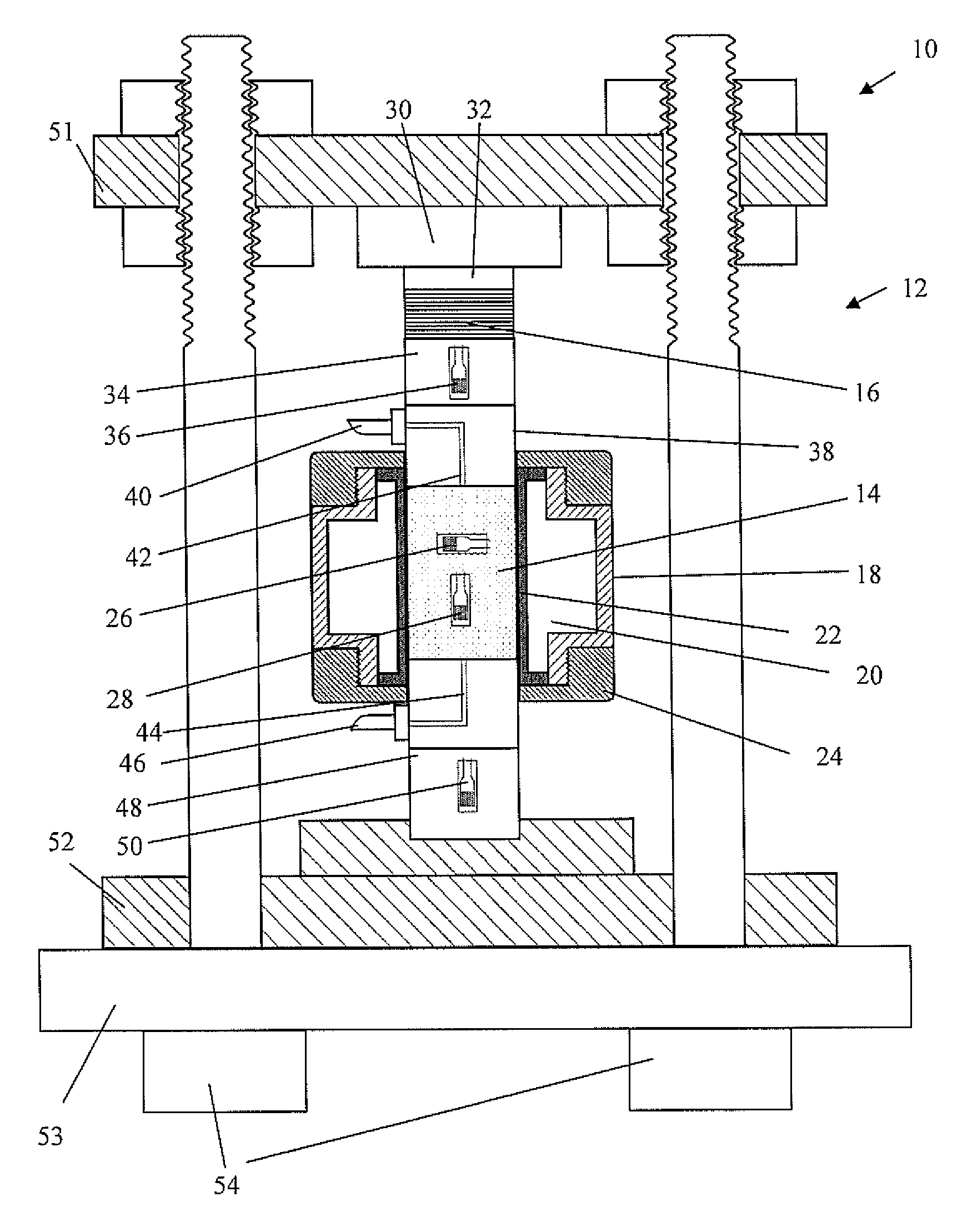
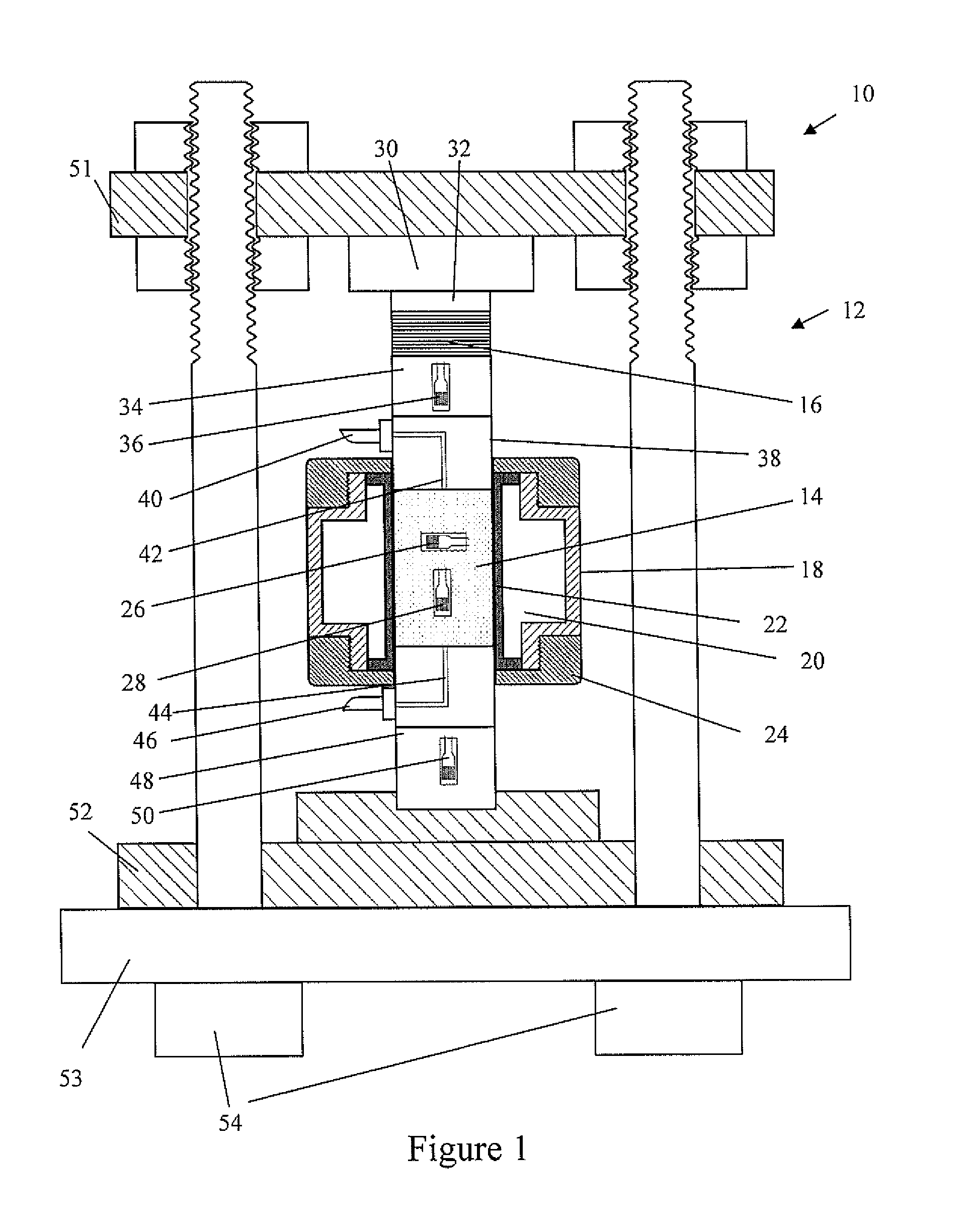
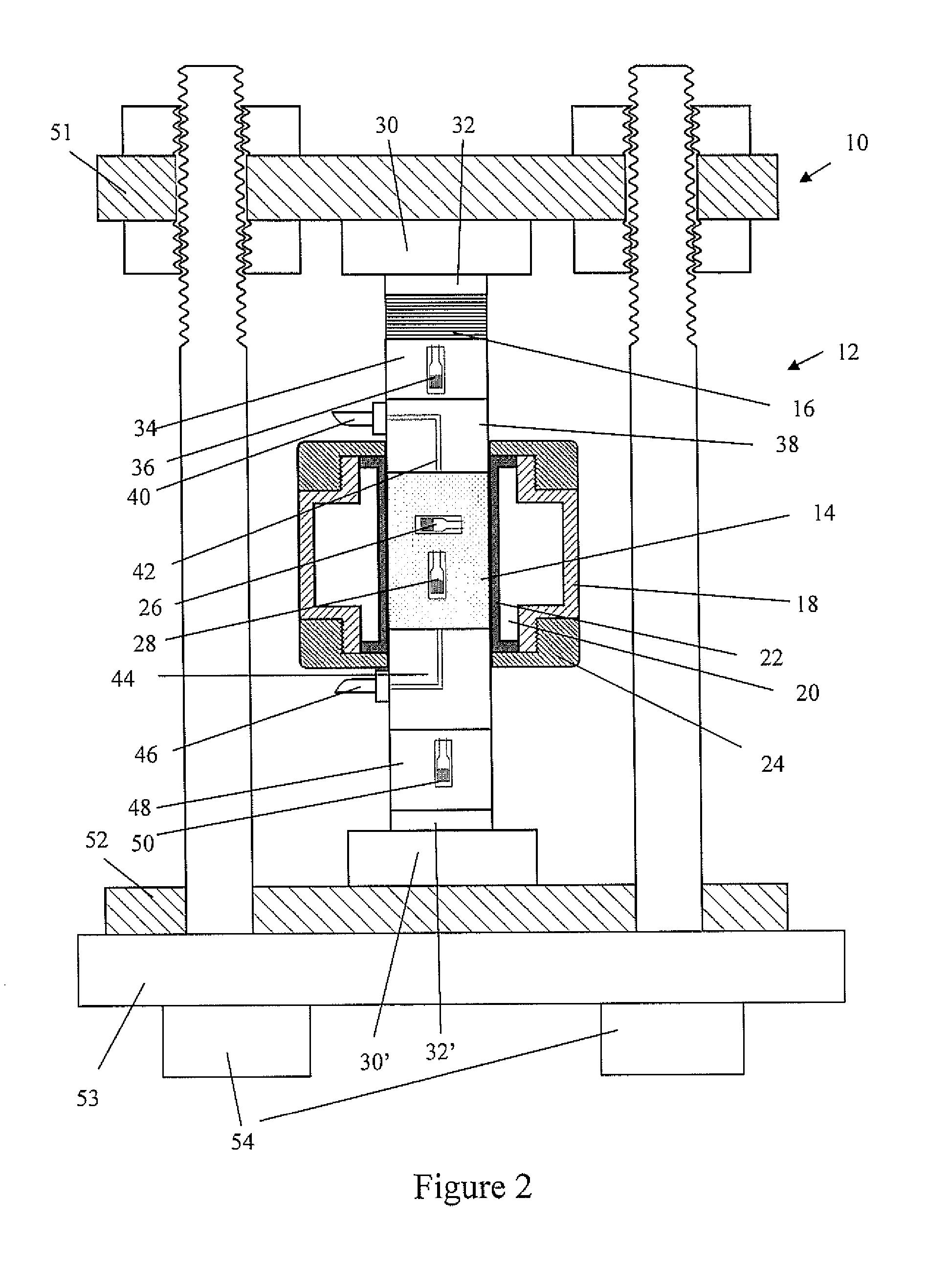
[0044]FIG. 1 shows an apparatus 10 for characterising mechanical properties of a sample. Typically, the mechanical properties will be elastic or anelastic properties of the sample, wherein the sample is a core sample taken from a region of geological interest for example for exploration.

[0045]The apparatus 10 is arranged to subject the sample to conditions to which it would be typically subjected to in a subsurface location and to allow appropriate measurements of mechanical properties to be made under such conditions.

[0046]To achieve this, the apparatus 10 comprises a structure 12 for supporting a sample 14 and for applying a first pressure to the sample 14 in a first direction. In this example, the first pressure is applied by a hydraulic pressure machine 30 having a piston 32 that directs the force in an axial direction with respect to the sample 14. The hydraulic machine 30 is in fluidal communication with a pressure source (not shown), such as via an appropriate hydraulic fluid...


PUM

PropertyMeasurementUnit
resonance frequencyaaaaaaaaaa
frequencyaaaaaaaaaa
frequencyaaaaaaaaaa

Abstract

The present disclosure provides an apparatus for characterising mechanical properties of a sample. The apparatus comprises a structure for supporting the sample and applying a first pressure in a first direction to the sample and an actuator for modulating the first pressure. The apparatus also comprises a pressure applicator containing a liquid and arranged to apply a second pressure to the sample in a second direction that is transversal to the first direction. Further, the apparatus comprises a pore pressure applicator arranged to apply a flow of a fluid through a porous sample such that a pore pressure is applied to the porous sample. In addition, the apparatus comprises a sensor for sensing a change in the sample in response to a change in a pressure experienced by the sample.

Description

FIELD OF THE INVENTION[0001]The present invention relates to an apparatus for characterising mechanical properties of a sample. In particular, though not exclusively, the present invention relates to an apparatus for simulating conditions that the sample would experience in a subsurface location, and for characterizing elastic or anelastic properties of the sample.BACKGROUND OF THE INVENTION[0002]Information obtained in geological surveys using sonic and / or seismic waves (relatively low frequency waves) needs to be interpreted.[0003]A common way of doing this is to take a sample, such as a core sample, from the region where the geological survey was taken and to subject the sample to typical subsurface conditions, such as stresses and pore fluid pressures. The sample is then analysed using ultrasonic waves (relatively high frequency waves) and obtained results are corrected such that at least some information for low frequency conditions can be estimated. However, such corrections i...

Claims


Application Information

Patent Timeline
Patent Type & Authority Applications(United States)
IPC IPC(8): G01N3/00
CPCG01N3/32G01N33/38G01N3/00G01N2203/0242G01N2203/0019
Inventor LEBEDEV, MAXIMMIKHALTSEVITCH, VASSILYLWIN, MARKGUREVICH, BORIS
Owner CURTAIN UNIV OF TECH
Why Eureka
Try Eureka