Relay busbar device with built-in current sensor for vehicle

a busbar device and vehicle technology, applied in electric devices, instruments, transportation and packaging, etc., can solve the problems of insufficient size reduction, complex structure, and increased cost, and achieve the effect of easy size reduction, good electromagnetic transducer characteristic, and high degree of freedom in molding

Active Publication Date: 2013-08-22
SUMITOMO ELECTRIC IND LTD +2
View PDF3 Cites 54 Cited by
  • Summary
  • Abstract
  • Description
  • Claims
  • Application Information

AI Technical Summary

Benefits of technology

[0013]An object of this invention is to reduce the size of a relay busbar device with a built-in current sensor for the power circuit of the inverter and motor in a vehicle adopting a structure in which the inverter and motor are housed in the same casing, or in which the two casings are in contact, or similar.
[0015]Because the plate is plate-shaped, in a vehicle adopting a structure in which the inverter and motor are housed in the same casing or the two casings are in contact, a large installation space is not required within the casing, and the plate can be easily interposed between two casings, thereby enabling the installation space of two casings to be reduced.
[0020]The face of the resin plate on the motor side is provided with a packing surrounding a circuit substrate on which are mounted the relay busbar, the magnetic core and the magnetic sensor; it is preferable that motor lubricating oil is prevented from leaking from within the motor to the outside by this packing. Further, similar packing can be provided on the face of the resin plate on the side opposite this packing.
[0022]The magnetic core can be formed from laminated steel plate, or can be formed of a compacted powder magnetic member, formed by pressure-molding magnetic particles which are individually insulated. A compacted powder core has such advantages as exhibiting a good electromagnetic transducing characteristic at high frequencies, a high degree of freedom in molding, and easy reduction of size, and in addition separation of the material when disposing of the relay busbar is easy, facilitating recycling. Further, compacted powder affords high dimensional precision, and is advantageous when mounting by fitting into a resin plate. Similarly to the relay busbar, the core can be integrally mold-formed when resin-molding the resin plate, or can be fitted into or otherwise mounted on the resin plate.

Problems solved by technology

When attempting to reduce the volume occupied by the inverter and motor, for a conventional relay busbar device the connection of the relay busbar with the inverter output terminal or with the motor input terminal employs a connector structure (see FIG. 1 and FIG. 2 of Japanese Patent Application Laid-open No. 2011-15586 and FIG. 5 of Japanese Patent Application Laid-open No. 2008-114839), and the structure becomes complicated; in addition, further reduction in size is demanded.
In the relay busbar device with a current sensor of Japanese Patent Application Laid-open No. 2011-209158 also, the entire current sensor is resin-molded, and the relay busbar penetrates into the molding, and the reductions in size and cost are not adequate.

Method used


Image

  • Relay busbar device with built-in current sensor for vehicle
  • Relay busbar device with built-in current sensor for vehicle
  • Relay busbar device with built-in current sensor for vehicle

Examples


Embodiment Construction

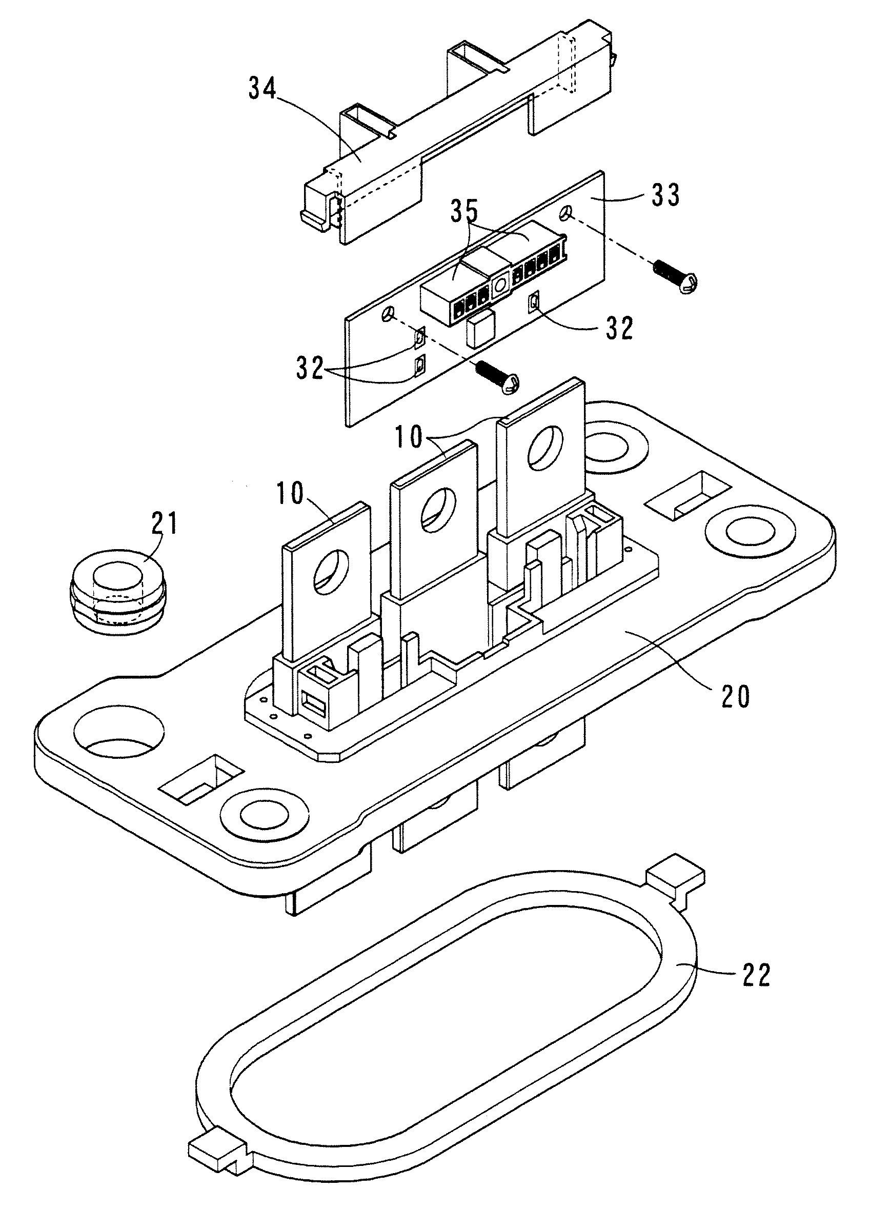
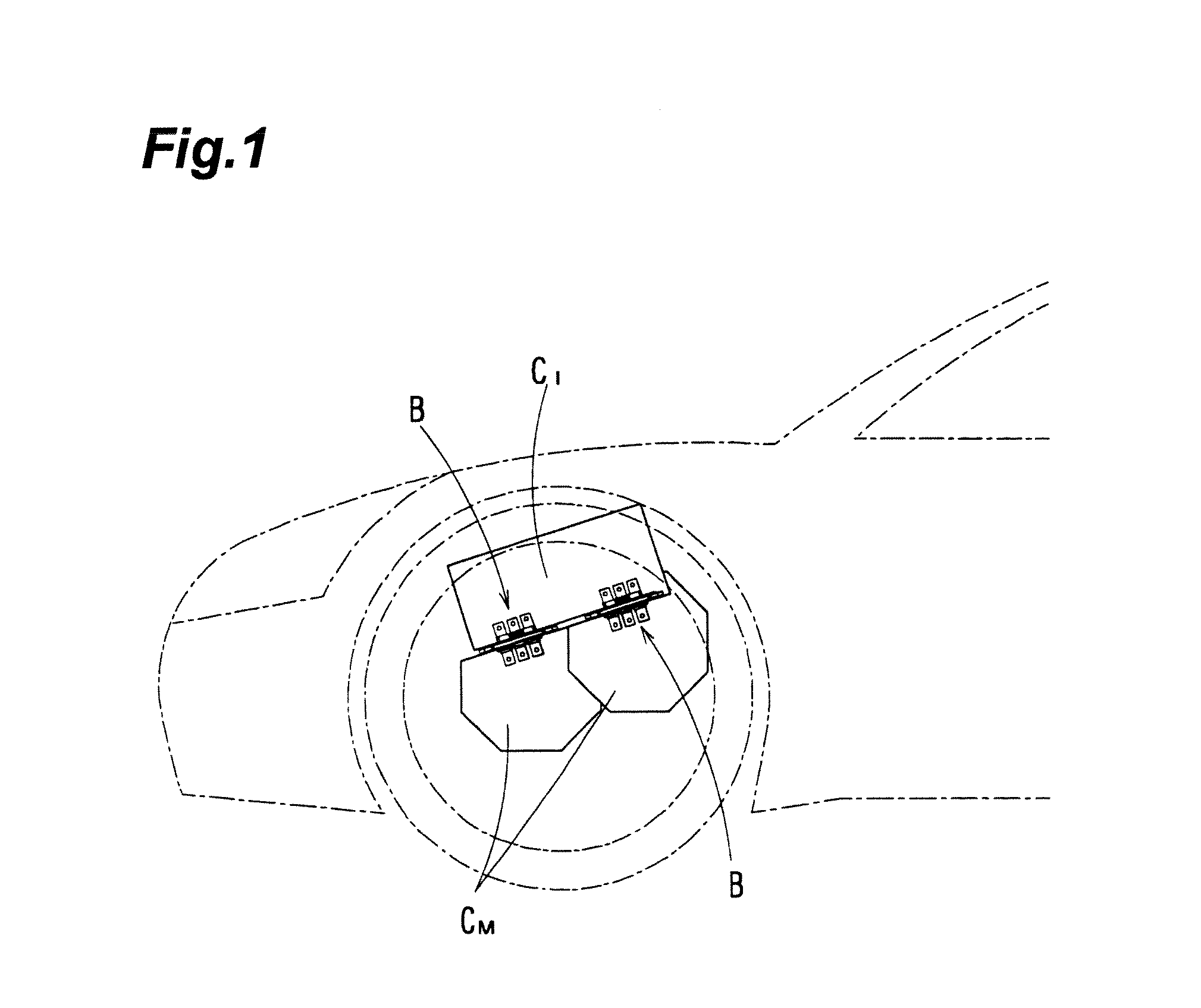
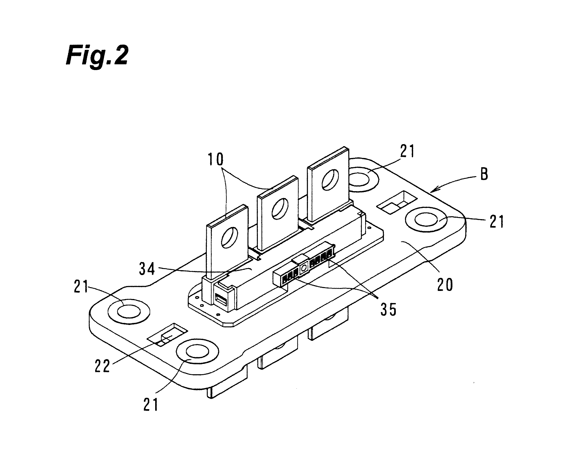
[0037]One embodiment of the invention is shown in FIG. 1 to FIG. 8; as shown in FIG. 1, the relay busbar device B of this embodiment is interposed between a motor casing CM and an inverter casing CI. The relay busbar device B comprises a relay busbars 10 formed from straight plates; a resin plate (base bracket) 20 through which the relay busbars 10 penetrate perpendicularly, and which is interposed between the two casings; and a current sensor 30 built into the resin plate 20.

[0038]Mounting holes are formed in the four corners of the resin plate 20, collars 21 are fitted into the holes, and by interposing between the two casings CM and CI and passing bolts through the collars 21 and fastening with nuts, the resin plate 20 is fastened to both of the casings CM and CI or to one of the casings. At this time, a rubber seal ring (packing) 22 is fitted onto the surface of the resin plate 20 on the side of the motor casing CM, and the intrusion of motor lubricating oil is prevented by this...


PUM


Abstract

A relay busbar device of one embodiment is a relay busbar device with a built-in current sensor, which is interposed between a motor casing and an inverter casing, and includes a relay busbar both ends of which enter into both of the casings; a resin plate, through which the relay busbar penetrates, and which is interposed between the two casings; a magnetic core, positioned within the resin plate and surrounding the relay busbar; and a magnetic sensor provided in a removed portion of the magnetic core. The relay busbar is mold-formed integrally with the resin plate during resin molding thereof, and changes in magnetic field occurring in the removed portion due to the current flowing in the relay busbar are detected by the magnetic sensor, and the value of the current flowing in the relay busbar is measured.

Description

CROSS-REFERENCE RELATED APPLICATIONS[0001]This application is based upon and claims the benefit of priority from Japanese Patent Application No. 2012-036323, filed on Feb. ref22, 2012, the entire contents of which are incorporated herein by erence.BACKGROUND OF INVENTION[0002]1. Field of Invention[0003]This invention relates to a relay busbar device with a built-in current sensor for vehicles, which forms a power circuit between a traction motor and an inverter in a vehicle equipped with the motor such as an electric vehicle (EV), fuel cell vehicle (FCV), hybrid vehicle (HV), and plug-in hybrid vehicle (PHV, PHEV), and which incorporates therein a sensor to detect the current flowing in the power circuit.[0004]2. Related Background Art[0005]Among vehicles equipped with this type of traction motor (hereafter “motor”), the power terminals of motors (including motor-generators) and generators and the inverter power terminals of power control units (PCUs) are connected using a relay bus...

Claims


Application Information

Patent Timeline
Patent Type & Authority Applications(United States)
IPC IPC(8): B60R16/03
CPCG01R15/207B60R16/03
Inventor OHASHI, SHINGOBABA, TAKESHISUZUKI, IZUMIKONDO, TOMOYUKI
Owner SUMITOMO ELECTRIC IND LTD
Why Eureka
Try Eureka