
Battery charger management system and method

a battery charger and management system technology, applied in data switching networks, transportation and packaging, sustainable buildings, etc., to achieve the effect of improving battery life and reducing battery material was

Active Publication Date: 2013-08-22
ADVANERGY
View PDF7 Cites 82 Cited by
  • Summary
  • Abstract
  • Description
  • Claims
  • Application Information

AI Technical Summary

Benefits of technology

The present invention is a battery charger management system and method that improves the lifespan of rechargable batteries compared to traditional charging systems. It automates the process of optimizing battery charging and longevity without modifying the hardware of the charging device. This results in a decrease in battery material waste and improves overall battery efficiency. The system works in conjunction with existing battery charging systems to provide seamless and optimized battery charging experiences.

Problems solved by technology

The active lifespan of rechargeable batteries has a direct impact on the cost to consumers of these products, the energy consumed to recharge these devices, and significantly impacts the environment as these batteries end their life cycle and are discarded.
However, a battery can only last half of that time if improperly used.
It is known that all rechargeable batteries suffer from the following problems:Full charges or under charges of batteries shorten the life span (or cycle life) of the batteries.
This effect is more serious for multi-cell batteries, which are widely used today.Batteries need to be charged and discharged (used) frequently—they are designed to be used.High temperature reduces the life span of the batteries.A battery calibration is needed every 2-3 months to keep the battery level monitoring system accurate.For some battery types, a recondition cycle is required every 2-3 months to remove the so called “memory effect” (batteries “remember” how much discharge was required on previous discharges and would only accept that amount of charge in subsequent charges).
As a result of these shortcomings, a rechargeable battery can become unusable well before the designed life span (typically half the designed life span of 5 years) due to improper charging and discharging.
Additionally, when a battery ages fast due to charging and discharging improperly, significant energy is wasted.
This implies more energy is turning into heat either when the battery is used (discharged) or when it is charged.When battery ages, self-discharge increases (to 10-20%), meaning energy is “dissipated” for no useful purposes.When fully charged, the battery chemical reaction increases and internal resistance increases even more, turning energy into wasted heat.As the battery ages, the internal capacity decreases (no longer holds enough energy), and the energy used to charge the battery is turned into reduced stored energy, another form of wasted energy.When the energy becomes heat, which increases the chemical reactions inside the battery, the situations mentioned above become even worse.
If the charging does not produce expected battery capacity due to aging, then the charging energy is wasted.
Assuming that half of the charging energy is wasted, it is not producing the expected energy charge for the battery.
Considering the number of hours people use battery-driven devices and the number of such devices, the overall energy waste associated with battery charging factored in a global scale is quite large.
However, all of these techniques require a disciplined, consistent practice over a long time.
This is a tedious if not impossible job for most users of rechargeable batteries.
This method lacks integration of historical battery information in the battery charge cycle.
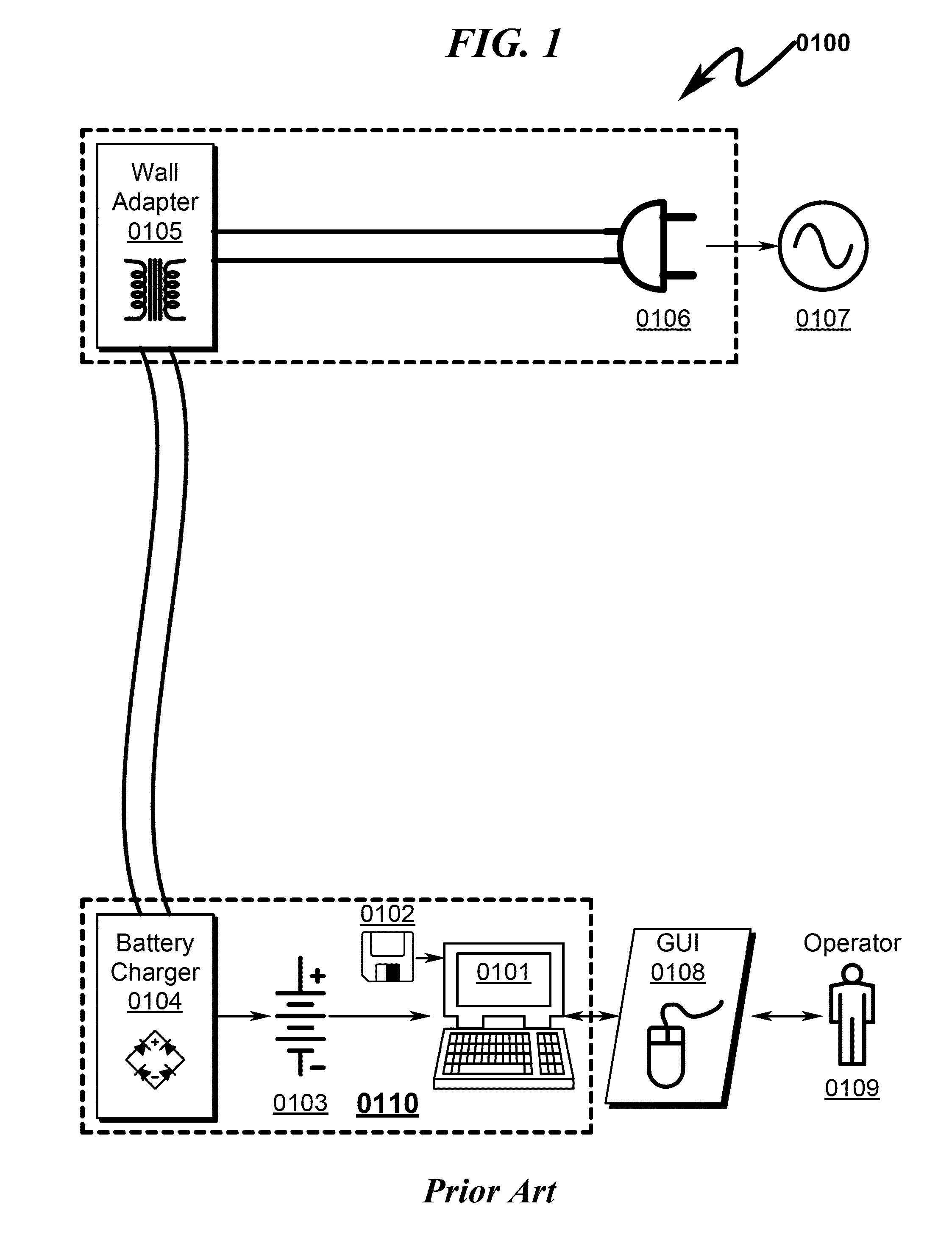
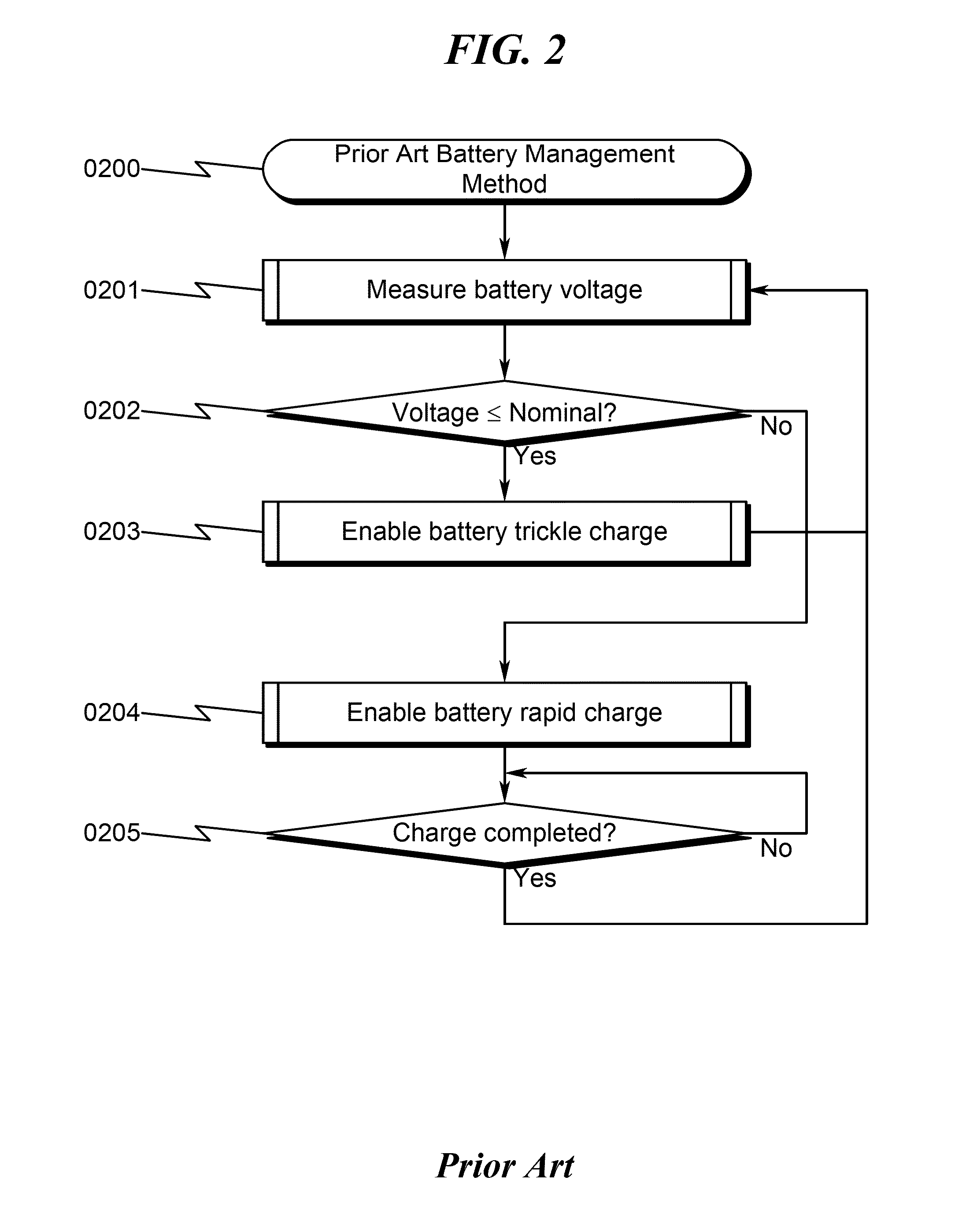
The prior art as detailed above suffers from the following deficiencies:Prior art battery charging systems / methods have as their goal the “full charging” of the battery in portable computer equipment, even though this goal results in reduced overall battery life.Prior art battery charging systems / methods generally do not compensate for environmental battery conditions.Prior art battery charging systems / methods generally do not regulate battery charge / discharge cycles independently.Prior art battery charging systems / methods generally do not automatically compensate for use characteristics of the portable computer equipment.Prior art battery charging systems / methods cannot be updated to accommodate a variety of battery types and chemistries.Prior art battery charging systems / methods do not perform battery calibration tests to dynamically determine the best charge / discharge profiles for the current state of the battery.Prior art battery charging systems / methods do not permit automatic battery lifecycle optimization to be retrofit into existing battery powered computing devices.
While some of the prior art may teach some solutions to several of these problems, the core issue of optimizing battery lifespan within a wide variety of portable battery powered computer equipment has not been addressed by the prior art.

Method used


Image

  • Battery charger management system and method
  • Battery charger management system and method
  • Battery charger management system and method

Examples


case 1

he Range of Absorotion Stage

[0187]As discussed earlier, the critical and defining attributes of a charging profile are the following:[0188]IS—the current at start of the Absorption Stage;[0189]IE—the current at the end of the Absorption Stage; and[0190]TA—the duration of Absorption Stage.

As an example,

IS=1 A, IE=10 mA, and TA=1.5 Hr.

[0191]There could be many ways to identify these two “turning points” of the charging profile. Here is one exemplary algorithm to find IS, IE, and TA:[0192]Given a set of input current and time samples {IK, TK}, K=1, 2, . . . , N, and the sample interval ΔT;[0193]Define εvs and εA, two configurable tolerance parameters used below. The algorithm described herein may typically initially let Ev=10 mV and εA=0.5 *ΔT[0194]Let ΔIK=I(K+1)−IK; K=1,2, . . . , N−1; the difference between two consecutive current samples (think of this as the derivative of the profile trajectory).[0195]Let δIK=ΔI(K+1)−ΔIK, K=1,2, . . . , N−2, the difference of the difference (think ...

case 2

; Find the Range of Bulk Stage as Well as Absorption Stage

[0202]If a battery is charged that has close to zero capacity then a more complete charging profile can be constructed. In this case, there are three critical points of interest: [IB, 0], [IS, TS] and [IE, TE]; where IB is the input current at the start of the Bulk Stage at time T=0, [IS, TS] and [IE, TE] are calculated as in CASE 1. With this profile it is known that the time range [0, TS] is for the Bulk Stage as well as the time range [TS, TE] being for the Absorption Stage. These time intervals are further detailed in FIG. 25 (2500).

case 3

Database

[0203]A battery database may be constructed that contains charging profiles obtained as in CASE 2 for all types of batteries available. The battery database may in some preferred embodiments be hosted on a web server. Users may specify via a user interface the brand name of the battery. The microcontroller (or other PSCU computing device) in the BCDM can go to the database to look for the charging profile for the given brand name. If the BCMD finds it, it may download the information, and uses that battery characteristic profile as the initial charging profile.

Updating the Charging Profile

[0204]As a battery ages, its charging profile may change. From time to time (say, for every 10 charges) its profile is updated (or relearned) with the sampled current data.

[0205]If different batteries are charged by the same battery charger, the BCMD may keep charging profiles for different batteries. Consumers can specify the brand name and assign an ID to a battery to be charged, so that ...


PUM


Abstract

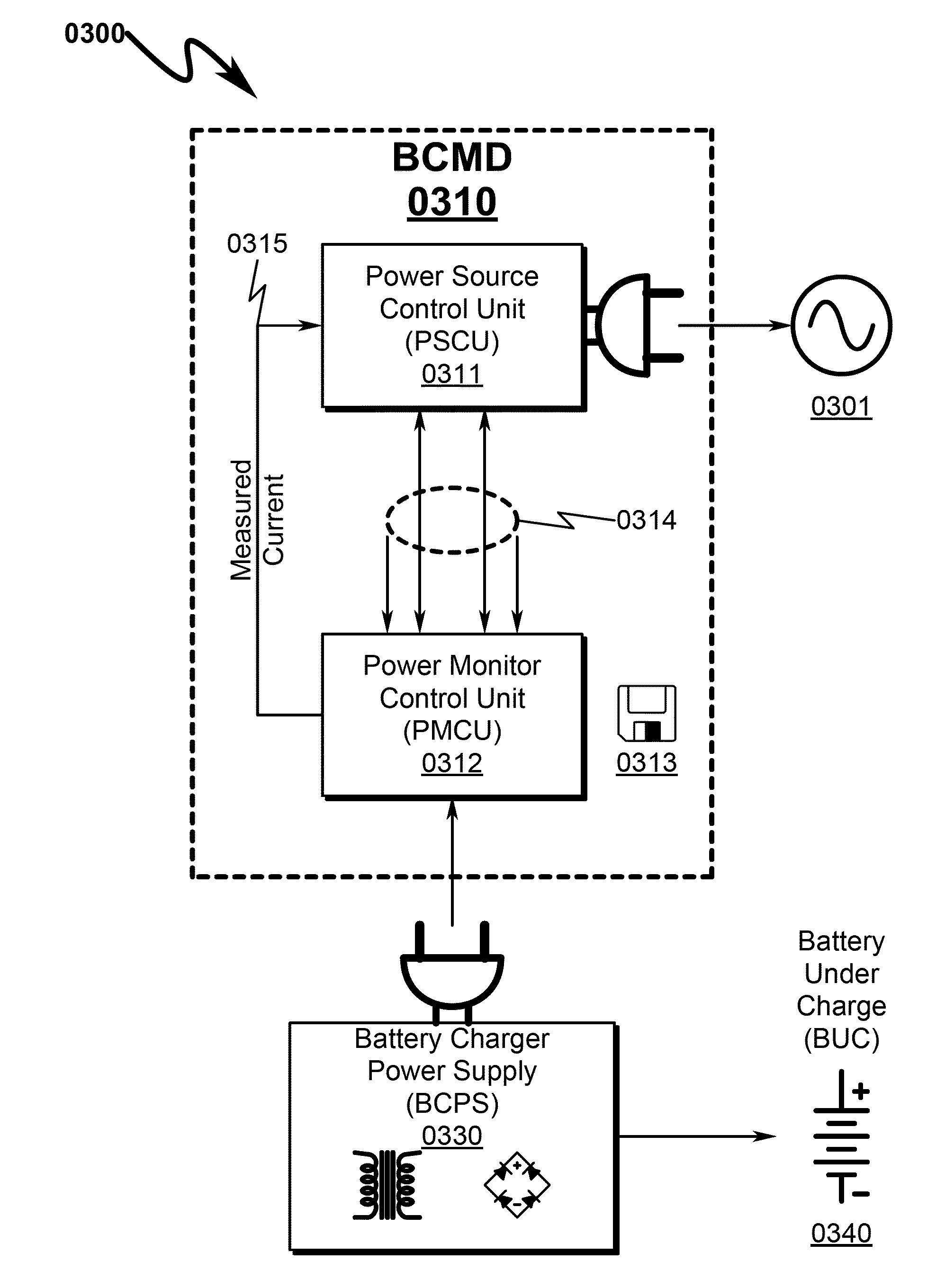
A battery charger management system / method implementing indirect execution of battery charging profiles is disclosed. The system utilizes a power source control unit (PSCU) to selectively switch a power supply source to a battery charging power supply (BCPS) that charges a battery. A power monitor control unit (PMCU) monitors the current consumed by the BCPS and reports this to the PSCU. The BCPS current consumption provides the PSCU a profile of the charging characteristics of the battery attached to the BCPS, allowing identification of the battery type and a determination of the optimal charging profile for the battery in its current charge state. The power source to the BCPS is switched by the PCCU in accordance with the determined optimal charging profile to optimally charge the battery. The PSCU may operate independently or in conjunction with wireless commands received from a mobile communication device (MCD).

Description

CROSS REFERENCE TO RELATED APPLICATIONS Continuation-in-Part Applications[0001]This application is a Continuation-In-Part (CIP) of U.S. Utility Patent Application for BATTERY MANAGEMENT SYSTEM AND METHOD by Jin (nmn) Lu, Todd Scott Kelly, and Lee (nmn) Cheung, filed electronically with the USPTO on Oct. 4, 2012, with Ser. No. 13 / 644,995, EFS ID 13911197, confirmation number 2226, docket AADVN.0102.[0002]This application claims benefit under 35 U.S.C. §120 and incorporates by reference U.S. Utility Patent Application for BATTERY MANAGEMENT SYSTEM AND METHOD by Jin (nmn) Lu, Todd Scott Kelly, and Lee (nmn) Cheung, filed electronically with the USPTO on Oct. 4, 2012, with Ser. No. 13 / 644,995, EFS ID 13911197, confirmation number 2226, docket AADVN.0102. This document and its parent Provisional Patent Application (Ser. No. 61 / 542,811, and Ser. No. 61 / 655,099) will be collectively referred to herein as “DOCUMENT BMSM”.U.S. Utility Patent Applications[0003]This application claims benefit ...

Claims


Application Information

Patent Timeline
Patent Type & Authority Applications(United States)
IPC IPC(8): H02J7/00
CPCH02J7/007H04L12/2807H04L12/2836Y02B40/90H02J7/0008H02J7/045H04L12/66H02J7/00041H02J7/00047Y02B40/00H02J7/04H02J7/00714
Inventor LU, JINKELLY, TODD SCOTTCHEUNG, LEE
Owner ADVANERGY
Learn More