
Dynamic power supply employing a linear driver and a switching regulator

a technology of switching regulator and linear driver, which is applied in the direction of dc-dc conversion, power conversion systems, instruments, etc., can solve the problems of not meeting the needs of a common smps nor a linear regulator, and the power conversion efficiency of such a linear regulator is poor, so as to improve the overall efficiency of the driver and reduce the voltage of the driver supply.

Active Publication Date: 2013-08-22
QUANTANCE
View PDF9 Cites 85 Cited by
  • Summary
  • Abstract
  • Description
  • Claims
  • Application Information

AI Technical Summary

Benefits of technology

The patent describes a method for improving the efficiency of a driver by using a switching regulator to step down the voltage supplied to it from a battery. This allows for better overall efficiency of the driver, even when using a battery as the first input voltage source. The method can also be used in RF power amplifiers to adjust the supply voltage based on the amplitude of the RF signal being amplified, reducing power consumption.

Problems solved by technology

Unfortunately, it cannot deliver sufficiently high frequency components of the power, because the low switching frequencies commonly used in these types of regulators (a limitation largely imposed by the magnetic and switching losses) bound the regulators bandwidth.
Linear regulators, on the other hand, may be designed to deliver high frequency components, but the power conversion efficiency of such a linear regulators is poor.
Thus neither a common SMPS nor a linear regulator can meet this need.
While conventional power supplies can typically change their voltage within s, this delay may prevent the digital circuitry from operating at peak efficiency.
Ripple typically occurs synchronously with the switching frequency of the switching regulator and can feed through to the output of the PA, causing unwanted distortion in the RF output signal.
These circuits, however, place a high burden on the linear regulator, as it requires the linear regulator to supply a large amount of excess current to modulate the voltage in the large reservoir capacitors needed by the switching regulator.
However, this series arrangement forces all the power delivered to the load to pass through the linear regulator, causing power dissipation in the linear regulator and substantially reducing the overall efficiency of the power supply.

Method used


Image

  • Dynamic power supply employing a linear driver and a switching regulator
  • Dynamic power supply employing a linear driver and a switching regulator
  • Dynamic power supply employing a linear driver and a switching regulator

Examples


Embodiment Construction

[0035]The figures and the following description relate to preferred embodiments of the present invention by way of illustration only. It should be noted that from the following discussion, alternative embodiments of the structures and methods disclosed herein will be readily recognized as viable alternatives that may be employed without departing from the principles of the claimed invention.

[0036]Reference will now be made in detail to several embodiments of the present invention(s), examples of which are illustrated in the accompanying figures. It is noted that wherever practicable similar or like reference numbers may be used in the figures and may indicate similar or like functionality. The figures depict embodiments of the present invention for purposes of illustration only. One skilled in the art will readily recognize from the following description that alternative embodiments of the structures and methods illustrated herein may be employed without departing from the principle...


PUM


Abstract

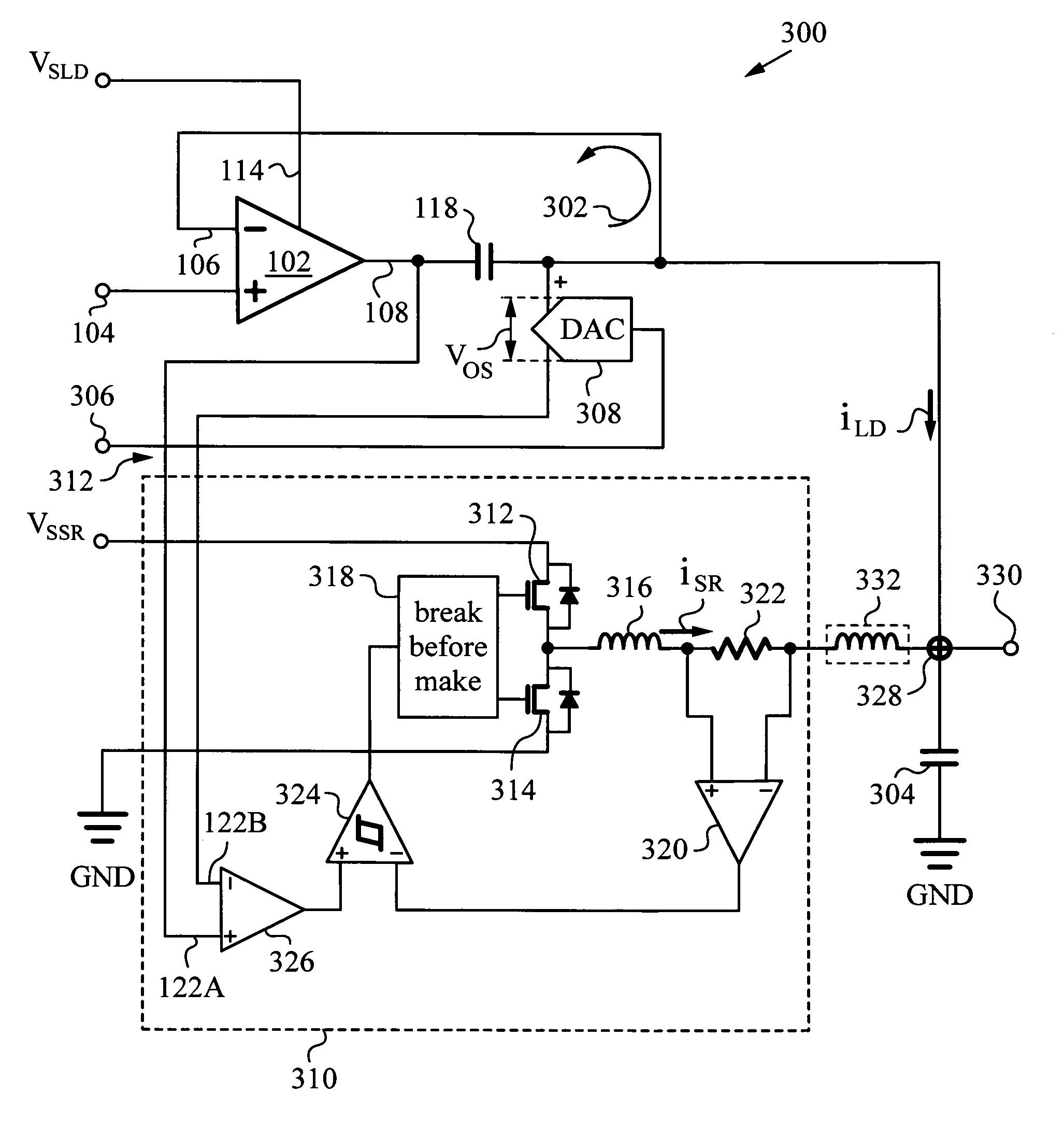
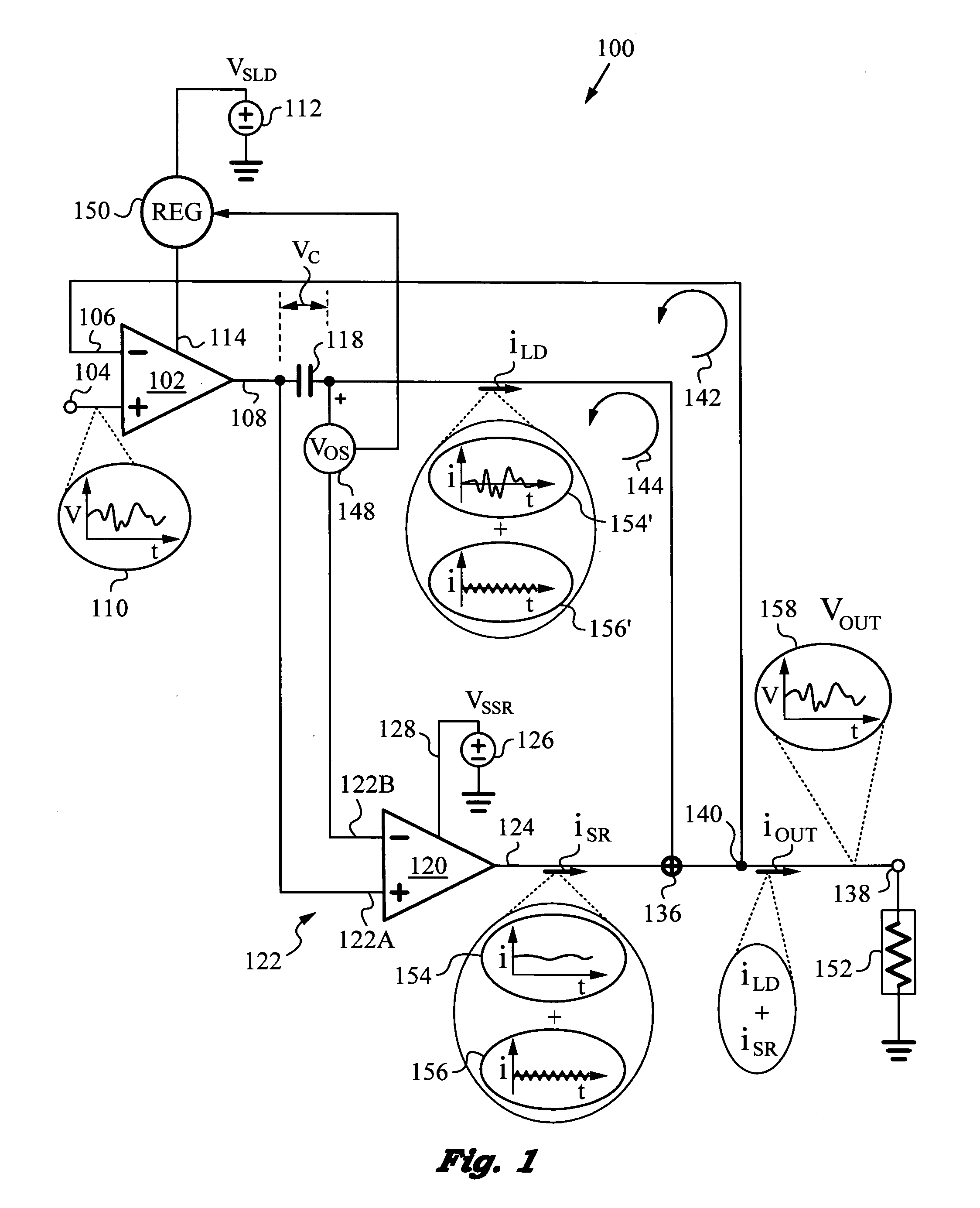
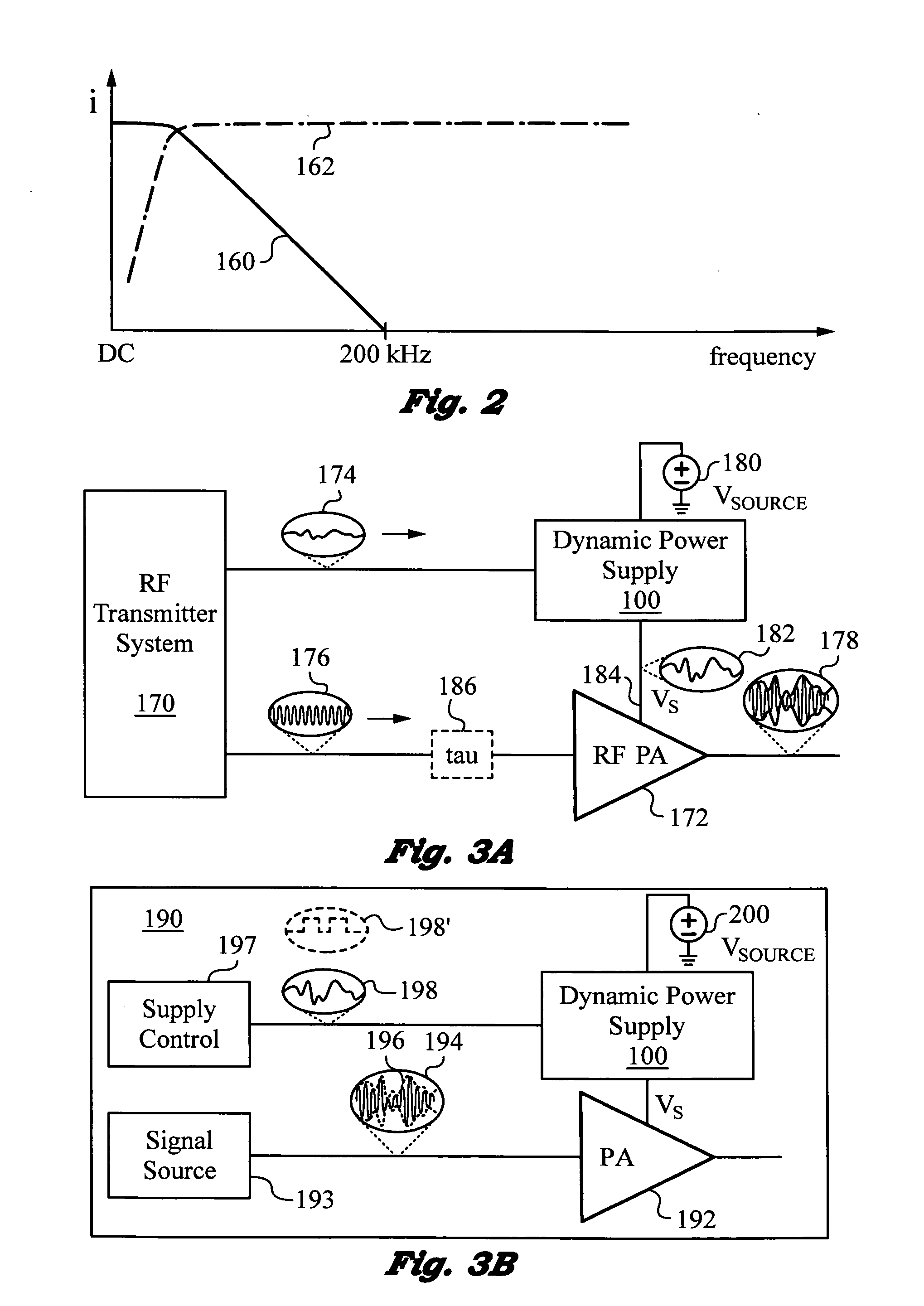
A highly efficient, high control bandwidth and high-speed power supply with a linear driver and a switching regulator for regulating an output based on a control signal. The linear driver has a first input for receiving the control signal and a second input connected to the output for receiving negative feedback. The driver's output is controlled by its two inputs and has a capacitor connected in series with it to generate a capacitor voltage VC responsive to the DC and low frequency components in the driver's output. The switching regulator has a control input and a regulator output connected in a regulator feedback loop. The control input receives capacitor voltage VC and the regulator feedback loop minimizes capacitor voltage VC. Thus, switching regulator takes over the generation of DC and low frequency components, while the linear driver provides high frequency output current components.

Description

RELATED APPLICATIONS[0001]This application is related to U.S. Application entitled “Low-Noise, High Bandwidth Quasi-Resonant Mode Switching Power Supply” filed on the same date.FIELD OF THE INVENTION[0002]This invention relates generally to dynamic power supplies utilizing linear drivers and switching regulators to provide output at high power efficiencies and over wide bandwidths.BACKGROUND ART[0003]There is often a need for a power supply circuit that is capable of delivering power with high frequency components (fast, dynamically changing voltage and current), at high overall power conversion efficiency. For example, a radio frequency (RF) power amplifier (PA), i.e., an RF PA, can be fed by an efficient power supply at a reduced voltage, allowing the PA to operate more efficiently (i.e., with lower power consumption).[0004]In an envelope tracking system, the power supply feeds the PA with a variable voltage that tracks the output power envelope of the PA. This provides for a redu...

Claims


Application Information

Patent Timeline
Patent Type & Authority Applications(United States)
IPC IPC(8): G05F1/46H03G99/00
CPCH02M3/156H02M2003/1566H02M2001/0045H02M1/14H02M1/0045H02M3/1566
Inventor TOURNATORY, DAVID C.G.TOMASZ, MARTIN A.
Owner QUANTANCE
Learn More