
Split feed distributor with feed supplied from below and thrown circumferentially

Inactive Publication Date: 2013-08-22
WEIGUO WU
View PDF10 Cites 23 Cited by
  • Summary
  • Abstract
  • Description
  • Claims
  • Application Information

AI Technical Summary

Benefits of technology

The present invention has the advantage of using negative pressure to convey feed through pipes, which results in a low crushing rate, wide distributing coverage, and even distribution. The feeding rate can be adjusted to allow for fast or slow distribution, and the residual feed can be avoided by quickly eating it up by fish or shrimp. The launching disc sucks up the feed from the pipe and throws it out, which is opposite to the natural tendency of the feed to move downwards. The distance between the feed-throwing mechanism and the feed-supplying mechanism depends on the size of the pond. The invention reduces workload and improves feeding efficiency by avoiding the need for hand-throwing feed.

Problems solved by technology

The feed distributor therein has two electric motors which complicates the configuration of the machine, and a limited coverage for feed-throwing, which is unsuitable for feeding shrimp, prawn, lobster, etc.
When a lot of them gather together in a small area, it results in overpopulation which is harmful to them as some are unable to obtain an adequate amount of food.
In addition, the supporting pole for fixing the electric motor would block the feed that is thrown and crush it.

Method used


Image

  • Split feed distributor with feed supplied from below and thrown circumferentially
  • Split feed distributor with feed supplied from below and thrown circumferentially
  • Split feed distributor with feed supplied from below and thrown circumferentially

Examples


Embodiment Construction

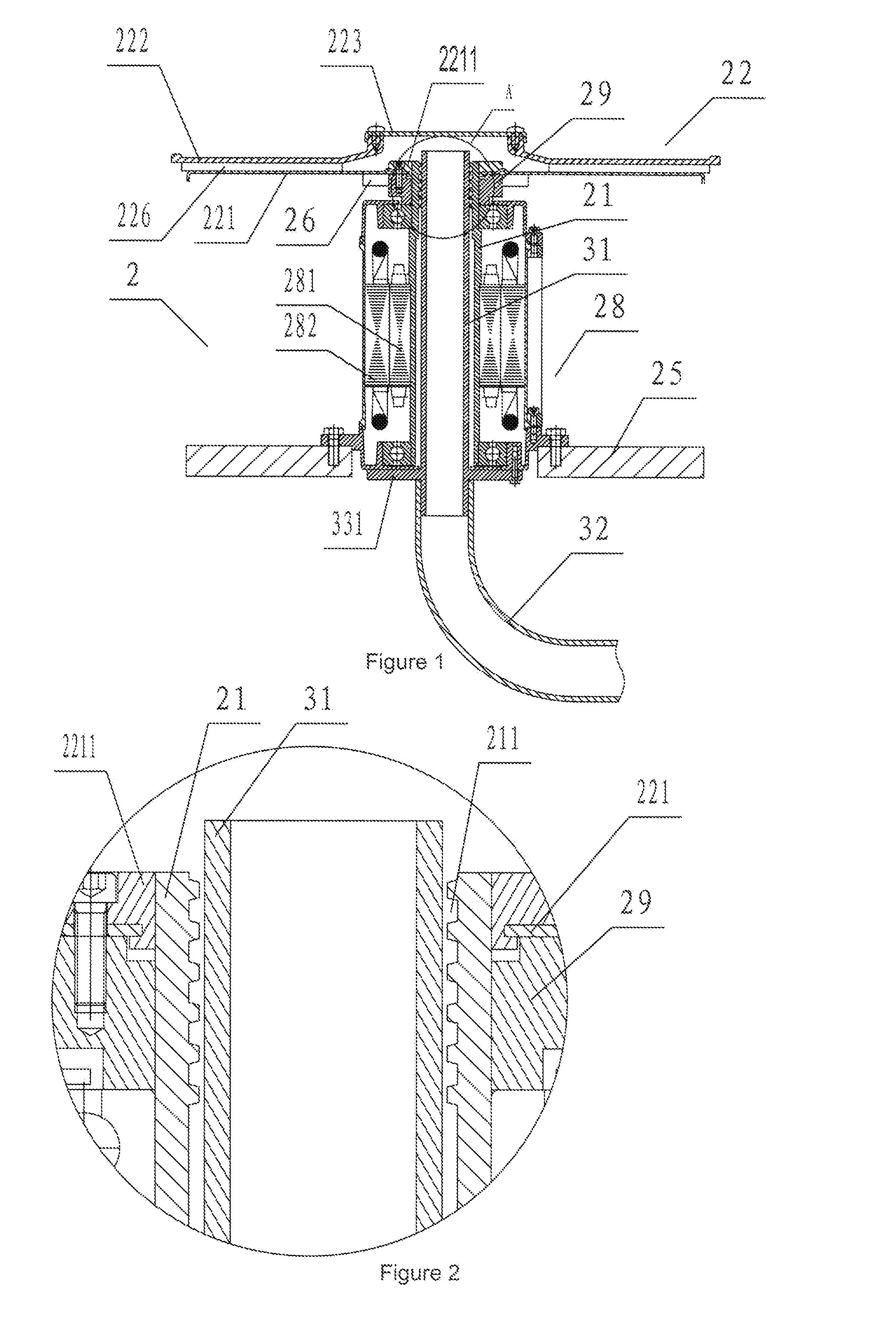
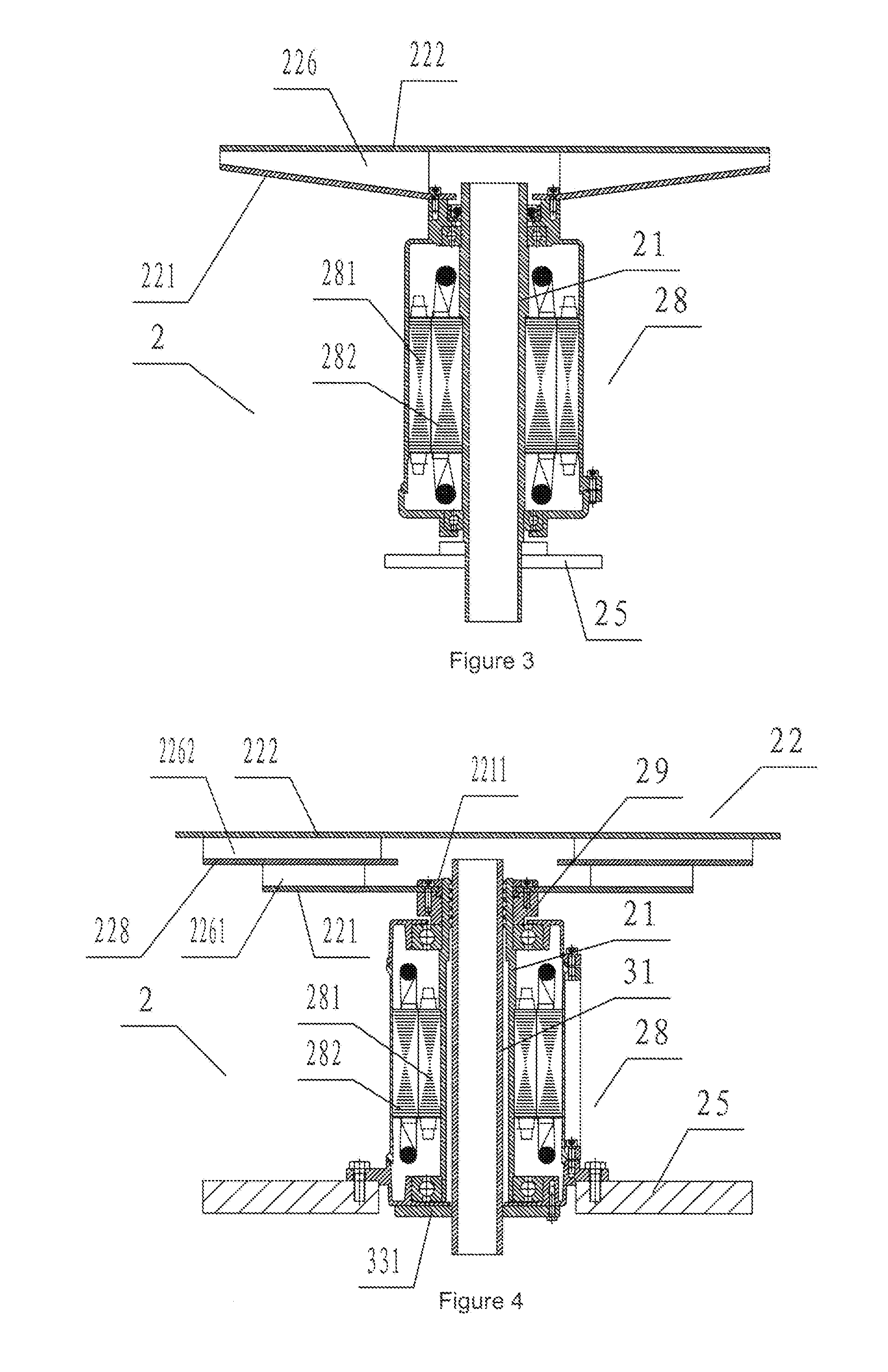
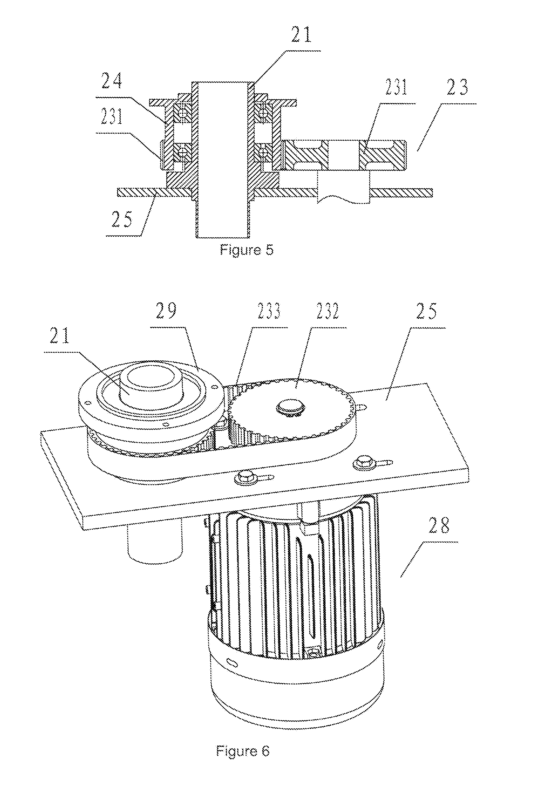
[0116]Referring first to FIG. 25, a feed distributor with feed supplied from below and thrown circumferentially comprises: a feed-supplying mechanism 1; a feed-throwing mechanism 2 for throwing feed from said feed-supplying mechanism 1, which has a launching disc 22 (FIG. 12) with a sealed top, feed outlets in its circumference and a feed inlet 2212 below (FIG. 8) and disposed on a hollow shaft 21 (FIG. 5) whose inner hole is opposed to said feed inlet 2212 below (FIG. 8); a feed-conveying mechanism 3 (FIGS. 13-15), by which feed supplied from said feed-supplying mechanism 1 is conveyed to said feed-throwing mechanism 2.

[0117]Referring to FIG. 1, said launching disc 22 rotates with said hollow shaft 21 by transmission means 23 (FIG. 5) when the power is on. Alternatively, said launching disc 22 can rotate by an electric motor with a hollow spindle which forms said hollow shaft 21. Still referring to FIG. 1, a discharge tube 31, which does not rotate, and connects with a conveying pi...


PUM


Abstract

A feed distributor used in fish ponds with feed supplied from below and thrown circumferentially comprises a feed-supplying mechanism, a feed-throwing mechanism and a feed-conveying mechanism by which feed supplied from said feed-supplying mechanism is delivered to said feed-throwing mechanism; the feed-supplying mechanism has a hopper which connects with a feed container above and a feed conveyor below. The feed-throwing mechanism has a launching disc with a sealed top, feed outlets in its circumference and a feed inlet below. The launching disc is disposed on a hollow shaft with an inner hole opposed to said feed inlet. The feed-throwing mechanism is disposed in pond and the feed supplying mechanism settles on a bank, feed is sucked into the feed-throwing disc and thrown circumferentially under negative pressure caused by rotation of the launching disc, and has a low crushing rate.

Description

CROSS-REFERENCE TO RELATED APPLICATION[0001]This application is a national stage application that claims the benefit of PCT application no. PCT / CN2011 / 074648 filed on May 25, 2011 (not yet published). The earliest priority date claimed is Nov. 13, 2010.FEDERALLY SPONSORED RESEARCH[0002]Not ApplicableSEQUENCE LISTING OR PROGRAM[0003]Not ApplicableSTATEMENT REGARDING COPYRIGHTED MATERIAL[0004]Portions of the disclosure of this patent document contain material that is subject to copyright protection. The copyright owner has no objection to the facsimile reproduction by anyone of the patent document or the patent disclosure as it appears in the Patent and Trademark Office file or records, but otherwise reserves all copyright rights whatsoever.BACKGROUND[0005]This present invention relates generally to a feed distributor in the field of mechanical technology in aquaculture. More particularly, this invention relates to a split feed distributor with feed supplied from below and thrown circ...

Claims


Application Information

Patent Timeline
IPC IPC(8): G01N21/47G01N21/64G01N21/59
CPCA01K61/02G01N21/64G01N21/59G01N21/47A01K61/80Y02A40/81
Inventor WEIGUO, WU
Owner WEIGUO WU
Learn More