Apparatus for dividing and supplying gas and method for dividing and supplying gas by use of this apparatus

a technology of apparatus and gas, which is applied in the direction of water supply installation, process and machine control, instruments, etc., can solve the problems of gas flow-in phenomenon, occurrence of overshooting phenomenon, and liable to easily occur, and achieves simple structure, high accuracy, and high-quality semiconductor products.

Active Publication Date: 2013-08-29
FUJIKIN INC
View PDF10 Cites 17 Cited by
  • Summary
  • Abstract
  • Description
  • Claims
  • Application Information

AI Technical Summary

Benefits of technology

[0027]In the present invention, switching in the opening and closing control of the motor-operated valves 7a to 7n disposed on the downstream side of the thermal-type mass flow sensors (MFMs) 6a to 6n of the divided flow passages is performed in such a way that the motor-operated valves 7a to 7n are maintained at a predetermined fixed opening degree without fully opening the motor-operated valves 7a to 7n when the pressure-type flow control system 4 that controls a total flow quantity Q of gas is in a non-operational state, whereas the motor-operated valves 7a to 7n undergo divided flow control by feedback control based on a flow detection signal Sm of the thermal-type mass flow sensors (MFMs) 6a to 6n when the pressure-type flow control system 4 is in an operational state and when the total flow quantity Q of gas has undergone flow control.
[0028]As a result, transitional flow-in (i.e., overshooting) of divided flows of gas occurring when the gas starts to be admitted into the divided flow passages L1 to Ln is completely prevented, and the gas can be supplied to the process chamber 13 through the divided flow passages L1 to Ln under highly accurate divided flow control, thus making it possible to manufacture higher-quality semiconductor products. Additionally, the switching-type controller 16 itself is merely required to be simple in structure and, therefore, a substantial rise in production costs, etc., is avoided.

Problems solved by technology

By the way, in the flow control device MFC (or FCS), when gas starts to be supplied, a gas flow-in phenomenon (so-called “overshooting” phenomenon) is liable to easily occur, and, especially in the thermal-type flow control device MFC, the occurrence of the overshooting phenomenon is inevitable.
Therefore, the occurrence of overshooting of gas in the gas dividing / supplying apparatus inevitably causes a decrease in operating efficiency of semiconductor manufacturing facilities, or a decrease in quality of products.

Method used


Image

  • Apparatus for dividing and supplying gas and method for dividing and supplying gas by use of this apparatus
  • Apparatus for dividing and supplying gas and method for dividing and supplying gas by use of this apparatus
  • Apparatus for dividing and supplying gas and method for dividing and supplying gas by use of this apparatus

Examples


Embodiment Construction

Modes for Carrying Out the Invention

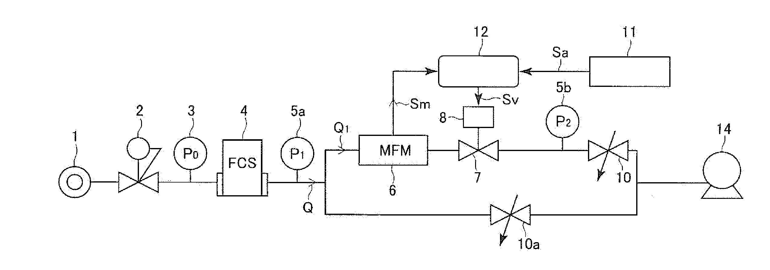
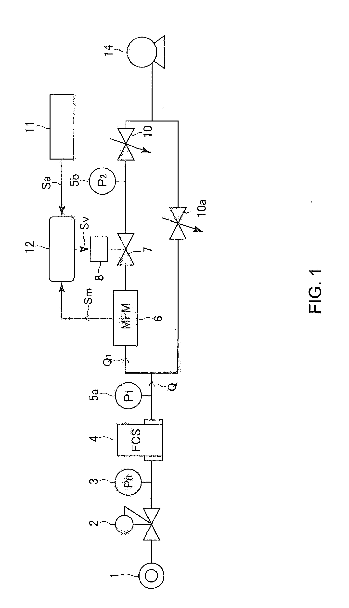
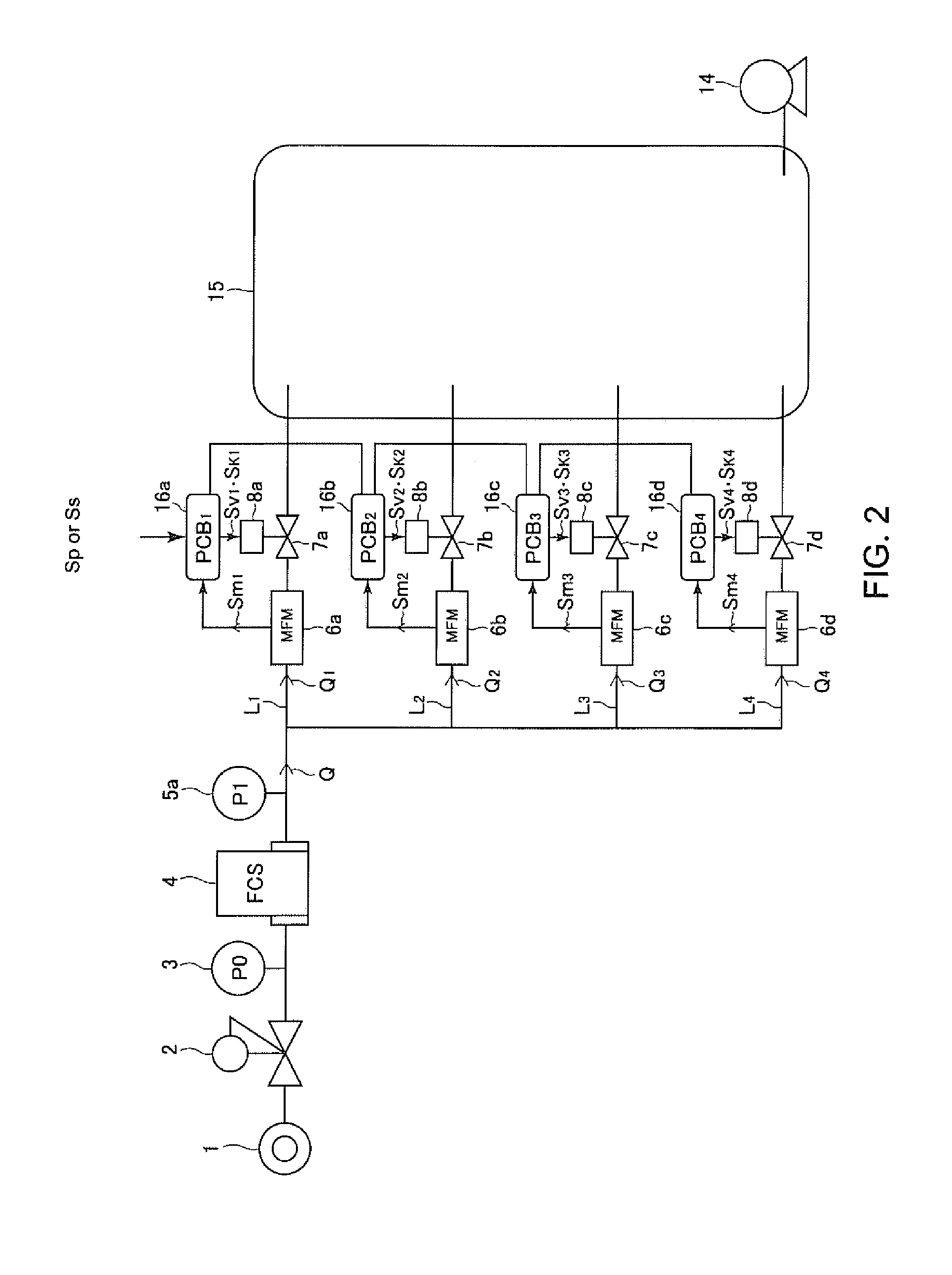
[0038]An embodiment of the present invention will be hereinafter described with reference to the drawings, wherein like parts are designated by like character references. FIG. 2 is a schematic view showing the whole structure of a gas dividing / supplying apparatus according to the present invention, and, in the present embodiment, predetermined flow quantities Q1 to Q4 of gas G are supplied to a large-sized process chamber 15 through divided flow passages L1 to L4 of four systems (L1 to Ln wherein n=4). In the apparatus of FIG. 2, the same reference symbol is given to the same component or the same member as in FIG. 1, FIG. 8, etc. In FIG. 2, reference symbol 15 designates the large-sized process chamber, reference symbols 16a to 16d designate switching-type controllers, reference symbols Sv1 to Sv4 designate valve driving signals, and reference symbols Sk1 to Sk4 designate valve opening control signals.

[0039]Referring to FIG. 2, in a steady state,...


PUM


Abstract

A gas dividing / supplying apparatus includes a pressure-type flow control system, a plurality of divided flow passages connected in parallel with each other and through which gas flowing from the pressure-type flow control system is divided and supplied to a process chamber, thermal-type mass flow sensors disposed in the divided flow passages, respectively, motor-operated valves disposed on a downstream side of the thermal-type mass flow sensors, respectively, and switching-type controllers that control opening and closing of the motor-operated valves, respectively, and, in the apparatus, the switching-type controllers perform switching between valve opening control for maintaining the motor-operated valves at a predetermined fixed valve opening degree based on a valve opening control command signal and divided flow control for regulating an opening degree of each of the motor-operated valves by feedback control based on a flow detection signal of the thermal-type mass flow sensor by a divided flow control command signal.

Description

[0001]This application claims priority from Japanese Patent Application No. 2012-043090, filed Feb. 29, 2012, the entire disclosure of which is incorporated herein by reference.TECHNICAL FIELD OF THE INVENTION[0002]The present invention relates to an improvement in a gas dividing and supplying system that divides and supplies gas from a pressure-type flow control system, disposed on a side of a gas supply source, to a plurality of divided flow passages, each of which is provided with a thermal-type mass flow sensor (MFM, which pertains to a thermal-type mass flow meter). More particularly, the present invention relates to a gas dividing and supplying apparatus that is capable of easily and reliably preventing the occurrence of excessive flow-in of gas (i.e., overshooting) at the beginning or initiation of supplying gas to each divided flow passage, and the present invention relates to a gas dividing and supplying method that employs the apparatus.BACKGROUND OF THE INVENTION[0003]In ...

Claims


Application Information

Patent Timeline
Patent Type & Authority Applications(United States)
IPC IPC(8): G05D7/06
CPCG05D7/0664G05D7/0641Y10T137/0368Y10T137/776F16K31/06G05D7/06G05D11/13
Inventor SAWADA, YOHEIIKEDA, NOBUKAZUDOHI, RYOUSUKENISHINO, KOUJI
Owner FUJIKIN INC
Why Eureka
Try Eureka