Method of forming a nitinol stent

a nitinol wire and stent technology, applied in the field of nitinol wire stent making, can solve the problems of difficult to form to an accurate geometry, difficult to generate a cost effective fixture for simple and complicated stent patterns, and difficulty in the formation of the stent itsel

Active Publication Date: 2013-08-29
MEDTRONIC VASCULAR INC
View PDF3 Cites 0 Cited by
  • Summary
  • Abstract
  • Description
  • Claims
  • Application Information

AI Technical Summary

Problems solved by technology

While using nitinol for stents is desirable, nitinol material presents some difficulties in the formation of the stent itself.
Nitinol materials in either the cold worked or heat-treated state can be easily sheared or stamped, but they are difficult to form to an accurate geometry, whether by forming wire shapes or die pressing.
When forming such a stent from a nitinol wire, complicated or specific design fixtures are required to hold the nitinol wire in the desired pattern throughout the heat setting, or heat treatment, process cycle.
It is also often difficult to generate a cost effective fixture for simple and complicated stent patterns.
Simpler wire forming methods available for stents made from other materials, where controlled plastic deformation of the wire into the desired shape allows for the wire to hold its shape through further processing, are generally not available for use with nitinol wires.
For example, and not by way of limitation, methods and devices for creating waveforms in a wire described in U.S. Application Publication Nos. 2010 / 0269950 to Hoff et al. and 2011 / 0070358 to Mauch et al., and co-pending U.S. application Ser. Nos. 13 / 191,134 and 13 / 190,775, filed Jul. 26, 2011, may not effectively be used to form nitinol wire stents.

Method used


Image

  • Method of forming a nitinol stent
  • Method of forming a nitinol stent
  • Method of forming a nitinol stent

Examples


Embodiment Construction

[0026]Specific embodiments of the present invention are now described with reference to the figures, where like reference numbers indicate identical or functionally similar elements.

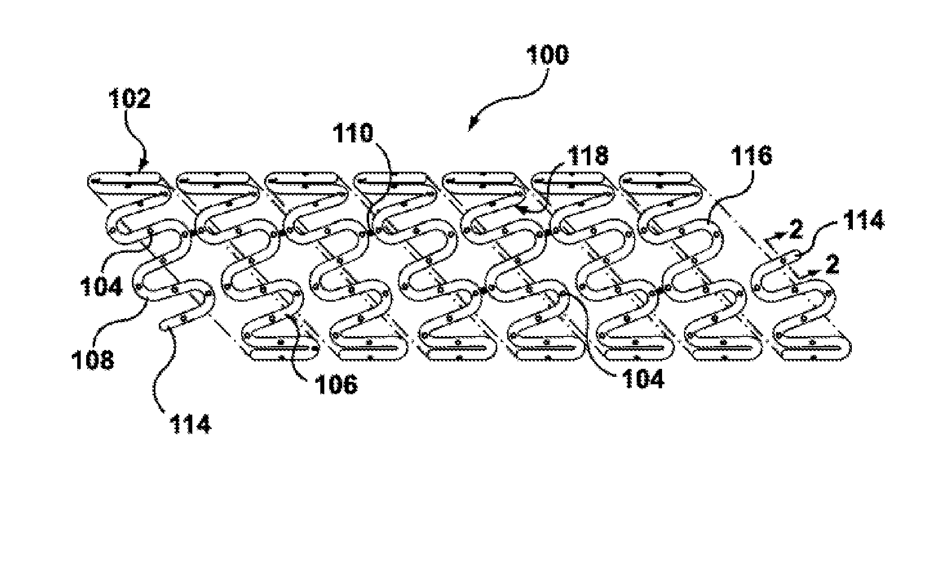
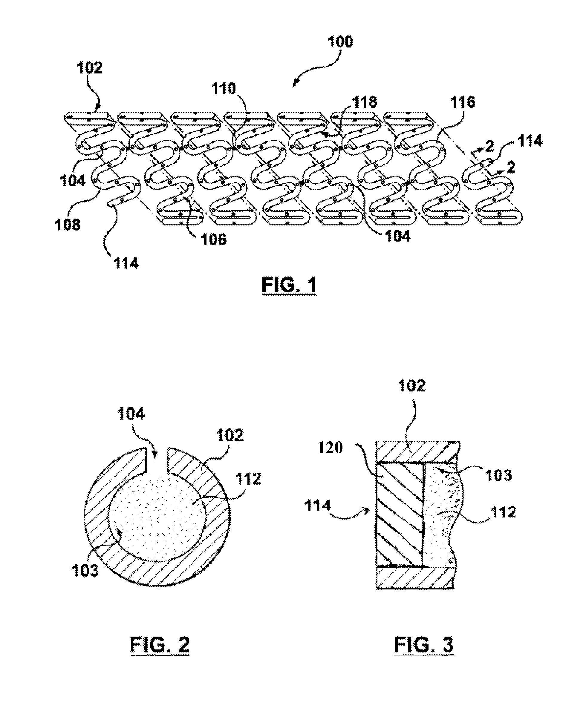
[0027]An embodiment of a stent 100 disclosed herein is shown in FIGS. 1-3. In particular, stent 100 is formed from a hollow wire 102, in particular, a hollow nitinol wire 102. The term “wire” as used herein means an elongated element or filament or group of elongated elements or filaments and is not limited to a particular cross-sectional shape or material, unless so specified. In the embodiment shown in FIG. 1, hollow wire 102 is formed into a series of generally sinusoidal waveforms including generally straight segments or struts 106 joined by bent segments or crowns 108. The wire with the waveforms formed therein is helically wrapped to form a tube, as shown in FIG. 1. In the embodiment shown in FIG. 1, selected crowns 108 of longitudinally adjacent sinusoids may be joined by, for example, fusion poin...


PUM

PropertyMeasurementUnit
body temperaturesaaaaaaaaaa
diameteraaaaaaaaaa

Abstract

A method of a forming a hollow, drug-eluting nitinol stent includes shaping a composite wire into a stent pattern, wherein the composite wire comprises an inner member, a nitinol intermediate member, and an outer member. After the composite wire is shaped into the stent pattern, the composite wire is heat treated to set the nitinol intermediate member in the stent pattern. After heat treatment, the composite wire is processed to remove the outer member and the inner member without adversely affecting the intermediate member. Openings may be provided through the intermediate member and the lumen of the intermediate member may be filled with a substance to be eluted through the openings.

Description

FIELD OF THE INVENTION[0001]The present invention relates to methods of making stents, and in particular, to methods of making stents from nitinol wires.BACKGROUND OF THE INVENTION[0002]Drug-eluting implantable medical devices have become popular in recent times for their ability to perform their primary function (such as structural support) and their ability to medically treat the area in which they are implanted. Further, stents made from shape memory materials, particularly nitinol, have become popular.[0003]Stents formed from nitinol include many characteristics desirable in an effective stent. Nitinol is a nickel-titanium alloy generally containing approximately 55-56% nickel and 44-45% titanium. Nitinol was developed by the Naval Ordinance Laboratory and receives its name from its component parts and the Naval Ordinance Laboratory (Nickel / Titanium / Naval Ordinance Laboratory). Specifically, stents formed from nitinol, with or without special coatings, have been found to be chem...

Claims


Application Information

Patent Timeline
Patent Type & Authority Applications(United States)
IPC IPC(8): B21F45/06
CPCA61L31/088A61L31/16A61F2250/0068A61F2240/001A61F2/88A61L31/022A61F2210/0014A61F2310/00023A61F2210/0076A61F2/915B23K2103/14C21D9/0068C22F1/006C22F1/10B21F45/008B21F45/00C23F1/12C23F17/00A61F2/90A61L2300/406A61L2300/41A61L2300/416A61L2300/42B23K26/40
Inventor THOMPSON, DUSTIN M.
Owner MEDTRONIC VASCULAR INC
Why Eureka
Try Eureka