Annuloplasty device and methods

a technology of annuloplasty and a valve leaflet, which is applied in the field of annuloplasty device and methods, can solve the problems of abnormal tension and angulation of the mitral valve leaflet, the less invasive surgical procedure is not as well developed for replacing abnormally functioning mitral valves, and the flow of regurgitants that can require repair or replacement of the valve, etc., and achieves high strength.

Active Publication Date: 2021-04-20
DRASLER WILLIAM JOSEPH +1
View PDF14 Cites 0 Cited by
  • Summary
  • Abstract
  • Description
  • Claims
  • Application Information

AI Technical Summary

Benefits of technology

[0013]In one embodiment the device is a single member stent-valve that is able to be used for Transcatheter Mitral Valve Replacement (TMVR) has a SE stent frame with a cylindrically-shaped or a curved waist portion and an upper bulb that is attached to the waist. This waist portion makes direct contact with the mitral annulus and ensures a tight seal against the mitral annulus; the upper stent bulb extends into the left atrium (LA) and outwards against the wall of the into the LA to provide additional seal against the LA to mitral annulus junction and to heal into the tissues above the mitral annulus to ensure that the mitral annulus does not expand further over time. The waist of the SE stent frame can have a limiting cable attached around its perimeter to ensure that the waist cannot expand further beyond a prescribed perimeter upon release from an delivery sheath that can ensure that an outward force is not being continuously applied to the mitral annulus. The outward force exerted by the SE waist to reach its full perimeter and expand the mitral annulus outward to a round shape can also be increased beyond the forces normally applied by a standard SE stent frame due to the presence of a limiting cable.
[0041]In another embodiment a cinch ring can be attached along the perimeter of the stent frame of the annuloplasty device. In this embodiment the stent frame can have an equilibrium perimeter that is equal to or somewhat greater (i.e., greater by 0-30% greater) than the mitral annulus perimeter. The stent frame can be a SE stent frame that is able to expand outwards into contact with the annulus along the entire perimeter of the annulus. Following delivery of the stent frame into apposition with the valve annulus, the barbs can be activated via an activating torus balloon. The cinch ring can then be placed under tension to cause the stent frame to reduce in diameter and perimeter and pull the annulus via the barb tips embedded in the annulus tissue to a smaller perimeter. The amount of perimeter reduction can be varied according with the amount of tension applied by the operator to achieve leaflet coaptation and reduction of mitral regurgitation as observed via color flow Doppler echocardiography. An expansion torus balloon can also be included in this embodiment if desired. The expansion torus balloon can be used to ensure apposition of the stent frame to the annulus along the entire perimeter; also the expansion torus balloon enables the use of a stent frame with a smaller equilibrium diameter that is approximately 80% (range 60-95%) of the diameter of the valve annulus. The expansion balloon can expand the stent frame outwards into contact with the valve annulus.

Problems solved by technology

Such regurgitant flow can require repair or replacement of the valve.
Such less invasive surgical procedures are not as well developed for replacing abnormally functioning mitral valves.
Often the regurgitant mitral valve is a result of excessive expansion of the left ventricle (LV) leading to abnormal tension and angulation imposed on the mitral valve leaflet.
It is therefore not acceptable to expand a stent indiscriminately outwards as is done in TAVR due to the potential for blockage of the LVOT by the anterior mitral valve leaflet.
The use of barbs or other fixation members to hold the TMVR device securely to the native mitral apparatus can create a set of potential clinical issues that are problematic to the patient.
Furthermore, activation of barbs via a standard dilation balloon can block blood flow through the mitral annulus during balloon inflation causing the patient to temporarily go without oxygen supply to the brain with its ensuing consequences.
Additionally, inflation of a standard balloon can cause the positioning of the stent-valve to become instantaneously displaced and hence inappropriately located across the mitral annulus due to blood pressure and blood flow generated by the LV.
This profile limitation has forced many of the TMVR devices to be delivered via the apex of the heart rather than through a more favorable transvascular and transseptal delivery approach.
The apical approach is not well suited to patients that are older in age or are of higher risk.
Without the stent-valve frame extending into the LV, the native leaflets can overhang into the replacement stent-valve and can interfere with stent-valve function.
What is needed is a stent-valve that does not cause impingement onto the LVOT and does not allow the native leaflets to interfere with the function of the replacement leaflets.
Valves of the heart including the mitral valve and tricuspid valve can become incompetent due to ischemia in the heart wall which can lead to enlargement of the heart and of the valve annulus.
Enlargement of the valve annulus can lead to heart failure and can also result in further enlargement of the heart and valve annulus.
These devices do not directly impart their forces onto the annulus and hence are not as effective as a surgically placed annuloplasty ring.
The procedure is time consuming and difficult to ensure that each of the screws is indeed placed into the proper fibrous tissue of mitral annulus such that the screws will indeed hold the tension necessary to pull the mitral annulus to a smaller perimeter.
Second, the frustum-shaped housing also allows the native mitral leaflets to be adequately exposed to blood flow across the native mitral leaflet surfaces (the inner flow surfaces that contact the blood flow from the LA to the LV and the outer surfaces that faces the myocardial wall) such that thrombosis is not generated and thrombo-emboli are not released with potential migration to the brain and resultant stroke.
This nonlinear path can result in the formation of a stagnation region between the native chamber wall and the covered stent-valve leading to thrombosis and the formation of thromboemboli that can be detrimental to the patient.
The stent-valve frame should be positioned across the valve annulus such that the potential for native valve leaflet prolapse cannot allow for entry or overhang of the native leaflet into the downstream end of the stent-valve and interfering with stent-valve function.

Method used


Image

  • Annuloplasty device and methods
  • Annuloplasty device and methods
  • Annuloplasty device and methods

Examples


Embodiment Construction

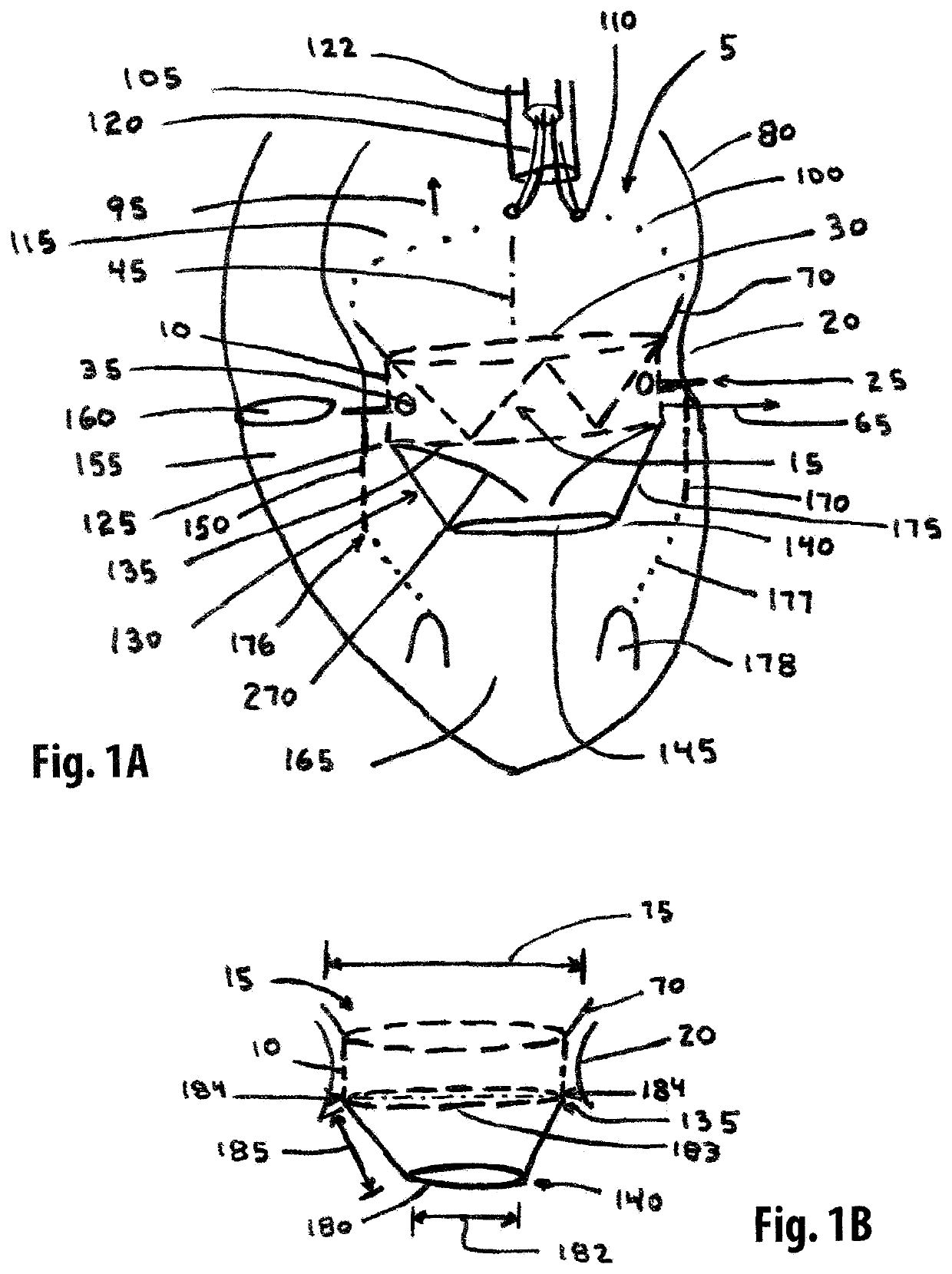
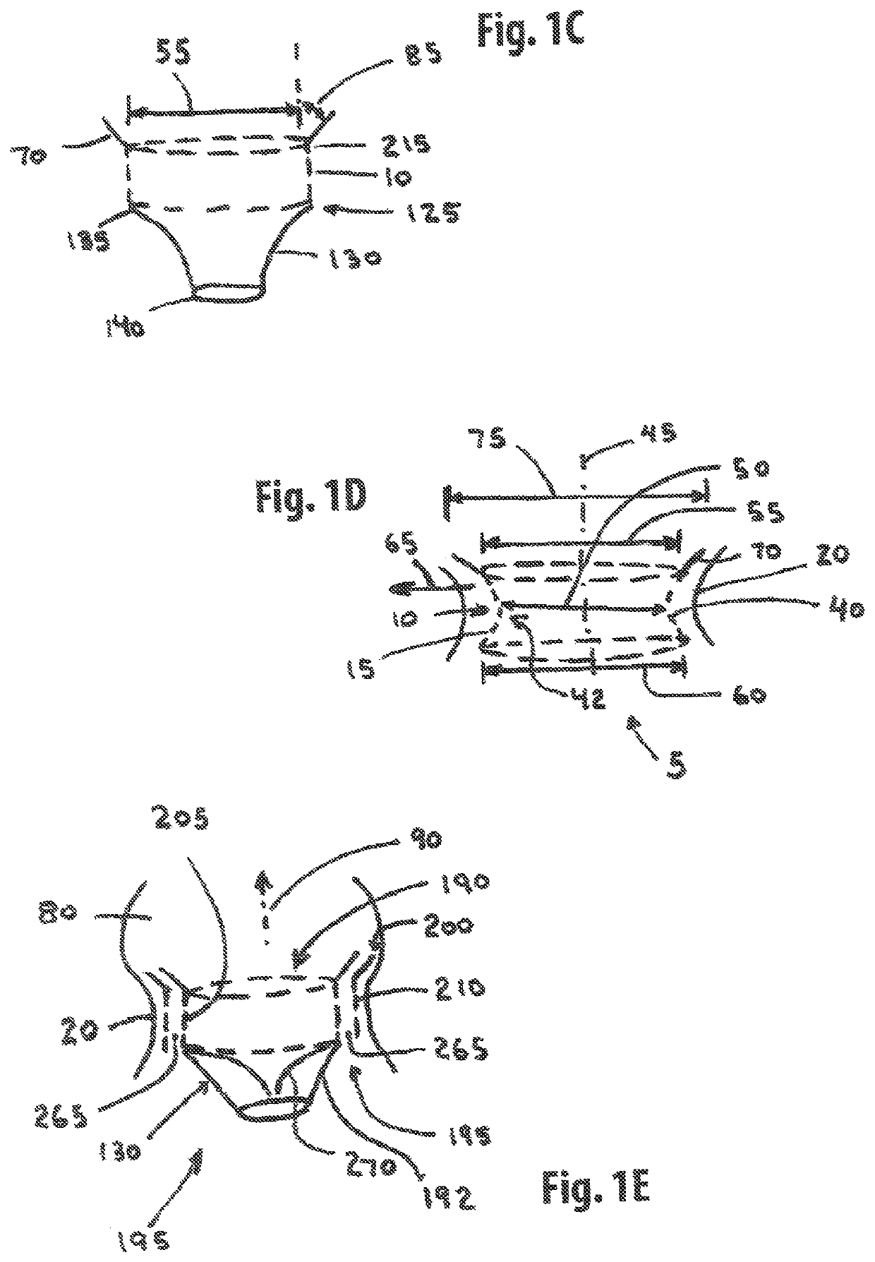
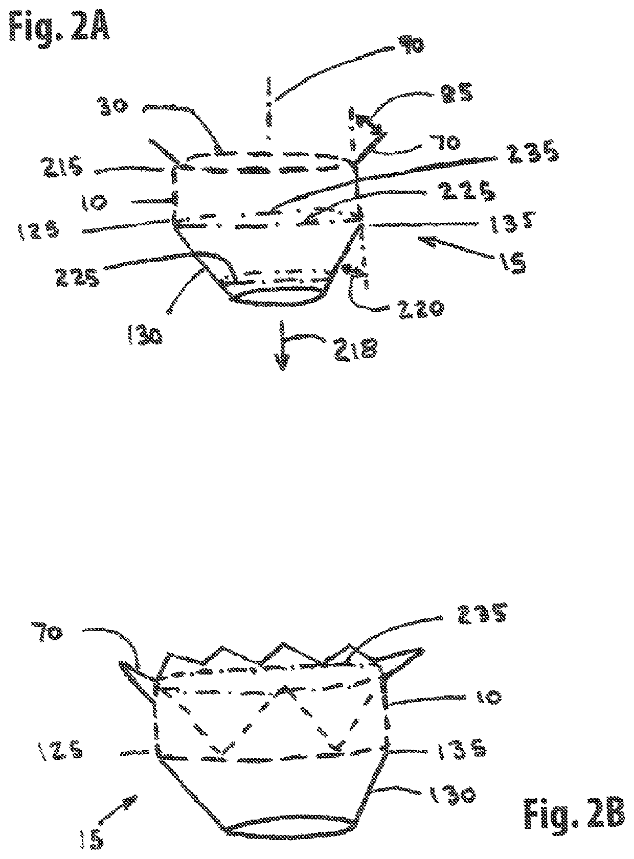
[0221]One embodiment of the present invention comprises a single member stent-valve that is intended as a transcatheter replacement valve for a valve of the heart; the single member stent-valve (5) is intended to be delivered within the lumen of the native heart valve and expanded outwards forming a functioning valve device having replacement leaflets. The valve device will be described in an application for its use as a transcatheter mitral valve replacement (TMVR) although it is understood that the invention can be applied to other valves found within the heart. The invention further comprises a dual member stent valve comprised of two components, a first component or support member and a second component or valve member. The first component is delivered across the annulus of the heart and affixed to the annulus or other native tissues of the heart; the first component does not interfere with function of native valve leaflets such that the mitral valve is fully functional while aw...


PUM


Abstract

An annuloplasty device formed from a Nitinol stent frame that expands into contact with the annulus above the native leaflets. A torus balloon activates barbs along the perimeter to fasten the stent frame to the annulus. A cinch ring is placed under tension to reduce the perimeter of the stent frame. The cinch ring and torus balloon are implanted along with the stent frame.

Description

CROSS REFERENCE TO RELATED APPLICATIONS[0001]This patent application makes reference to and thereby incorporates all information found in the nonprovisional patent application numbered: Ser. No. 15 / 457,626 entitled Two Component Mitral Valve filed 13 Mar. 2017 by William J. Drasler, et. al., and nonprovisional patent application numbered: Ser. No. 16 / 147,823 entitled Straddle Annular Mitral Valve filed on 30 Sep. 2018 by William J. Drasler et. al.; also, this patent application makes reference to and incorporates all information found in provisional patent applications numbered: 62 / 614,451 entitled Retractable Barb Straddle Mitral Valve filed 7 Jan. 2018 by William J. Drasler, and 62 / 618,183 entitled Annuloplasty Device with Torus Balloon filed 17 Jan. 2018 by William J. Drasler.BACKGROUND OF THE INVENTION[0002]Valves of the heart including the aortic valve, mitral valve, and tricuspid valve can become hardened from atherosclerotic plaque and calcium and no longer function normally....

Claims


Application Information

Patent Timeline
Patent Type & Authority Patents(United States)
IPC IPC(8): A61F2/24
CPCA61F2/2445A61F2/2418A61F2/2433A61F2/2442A61F2/2466A61F2220/0016A61F2230/0065A61F2250/001A61F2250/0003A61F2250/006A61F2250/0013A61F2210/0014A61F2220/0075
Inventor DRASLER, WILLIAM JOSEPHDRASLER, II, WILLIAM JOSEPH
Owner DRASLER WILLIAM JOSEPH
Why Eureka
Try Eureka