
Surface emitting multiwavelength distributed-feedback concentric ring lasers

a concentric ring, multi-wavelength technology, applied in semiconductor lasers, optical radiation measurement, instruments, etc., can solve the problem of limiting the overall usefulness of devices in other fields

Active Publication Date: 2013-08-29
THORLABS QUANTUM ELECTRONICS
View PDF11 Cites 14 Cited by
  • Summary
  • Abstract
  • Description
  • Claims
  • Application Information

AI Technical Summary

Benefits of technology

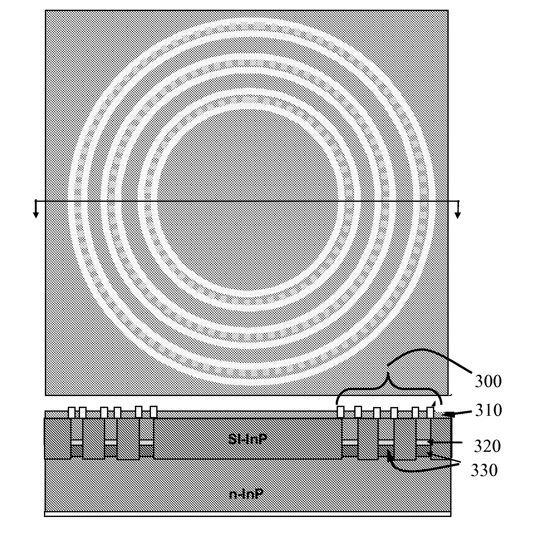
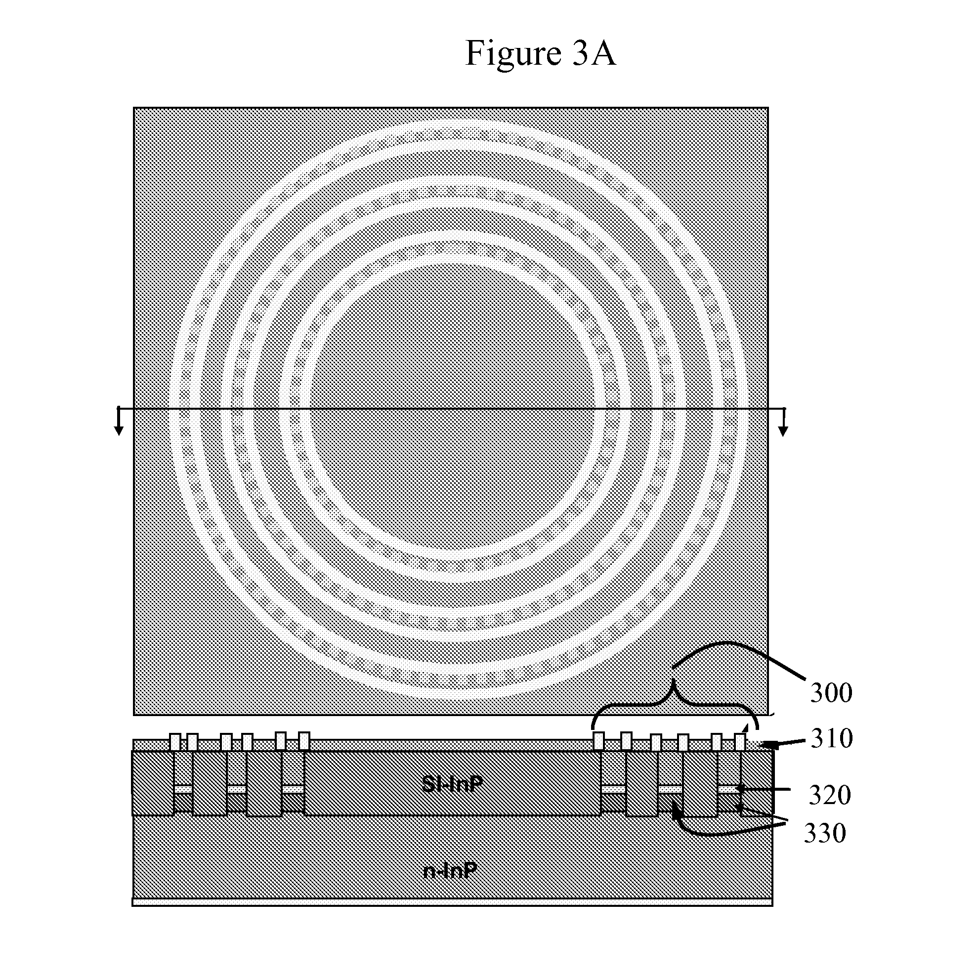
This patent describes two embodiments of lasers with different configurations and methods of operation. The first embodiment has multiple layers of gain material that generate photons through intersubband transitions. The laser sections are separated by an electrical isolation region. The laser has a wavelength range of 2.5 μm to 15 μm, and the active region has at least one, two, or three active stacks. The laser may operate in pulsed or continuous mode, and all sections may fire simultaneously or sequentially. The second embodiment describes using the laser to detect signals from a sample by applying the laser to the sample and collecting the light after it has interacted with the sample. The laser wavelength is in the mid-infrared region, and the sample may be in solid, gas, or liquid phase. The collected light provides information on mid-infrared absorbance or reflectance of the sample. These lasers and methods provide new tools for research and applications in the mid-infrared region.

Problems solved by technology

However, the limited tunability of DFB lasers presents a number of problems and limits the overall usefulness of the devices in other fields.

Method used


Image

  • Surface emitting multiwavelength distributed-feedback concentric ring lasers
  • Surface emitting multiwavelength distributed-feedback concentric ring lasers
  • Surface emitting multiwavelength distributed-feedback concentric ring lasers

Examples


Embodiment Construction

[0011]The present invention can be understood more readily by reference to the following detailed description, drawings, examples, and claims, and their previous and following description. However, before the present compositions, articles, devices, and methods are disclosed and described, it is to be understood that this invention is not limited to the specific compositions, articles, devices, and methods disclosed unless otherwise specified, as such can, of course, vary. It is also to be understood that the terminology used herein is for the purpose of describing particular aspects only and is not intended to be limiting.

[0012]The following description of the invention is provided as an enabling teaching of the invention in its currently known embodiments. To this end, those skilled in the relevant art will recognize and appreciate that many changes can be made to the various aspects of the invention described herein, while still obtaining the beneficial results of the present inv...


PUM


Abstract

Multi-surface emitting mid-IR multiwavelength distributed-feedback quantum cascade ring lasers laid out in a concentric circle are disclosed. The lasers utilize quantum cascade core designs to produce optical gain in the mid-infrared region and may generate several wavelengths simultaneously or sequentially. Methods of making along with methods of using such devices are also disclosed.

Description

CROSS-REFERENCE TO RELATED APPLICATIONS[0001]This application claims the benefit of priority under 35 U.S.C. §119 of U.S. Provisional Application Serial No. 61 / 604170 filed on Feb. 28, 2012 the content of which is relied upon and incorporated herein by reference in its entirety.FIELD[0002]The present specification generally relates to semiconductor-based lasers and, more specifically, to distributed feedback lasers in the mid-infrared region that have an active core made of concentric rings to generate several wavelengths simultaneously or sequentially. Methods of making and using such devices are also disclosed.TECHNICAL BACKGROUND[0003]Distributed feedback (“DFB”) lasers are a solid state diode laser technology that incorporates a diffraction grating into the active region of the laser. The DFB design allows for the emission of stable, single wavelengths that are slightly tunable via temperature change. DFB lasers are widely used in optical communication applications where the dev...

Claims


Application Information

Patent Timeline
IPC IPC(8): H01S5/32G01N21/59
CPCH01S5/183H01S5/18308H01S5/18397B82Y20/00H01S5/32G01N21/59H01S5/3402H01S5/187H01S5/42H01S5/4087H01S5/2275H01S5/2224H01S5/227H01S5/1071
Inventor CANEAU, CATHERINE GENEVIEVEXIE, FENGZAH, CHUNG-EN
Owner THORLABS QUANTUM ELECTRONICS
Learn More