LED retrofit lamp

a technology for retrofitting lamps and led lamps, applied in the field of led retrofit lamps, can solve problems such as difficulties, and achieve the effect of enhancing the power factor of the overall setup and enhancing the operation

Active Publication Date: 2013-08-29
KONINKLIJKE PHILIPS ELECTRONICS NV
View PDF2 Cites 94 Cited by
  • Summary
  • Abstract
  • Description
  • Claims
  • Application Information

AI Technical Summary

Benefits of technology

[0075]The operation according to said third and fourth timing control parameters allows an enhanced operation, when using two lamps according to the invention with a rapid start type of ballast, because the shunt periods of the two lamps do not substantially overlap.
[0076]Due to the design of said rapid start type of ballast unwanted losses may occur due to excessive current flow in case the switching devices of both lamps would be set to the conductive state simultaneously. Accordingly, the power factor of the overall setup can be enhanced when using the inventive lamp with a dual lamp rapid start type of ballast.

Problems solved by technology

While this fact is advantageous for the present efforts for energy conservation, difficulties might arise when retrofitting a fixture which is designed for a nominal power.
Depending on the circuit design of the fixture, the differing current draw may result in significant electrical problems, such as overheating of the ballast or an inacceptably low power factor when operating a LED lamp with such fixture.

Method used


Image

  • LED retrofit lamp
  • LED retrofit lamp
  • LED retrofit lamp

Examples


second embodiment

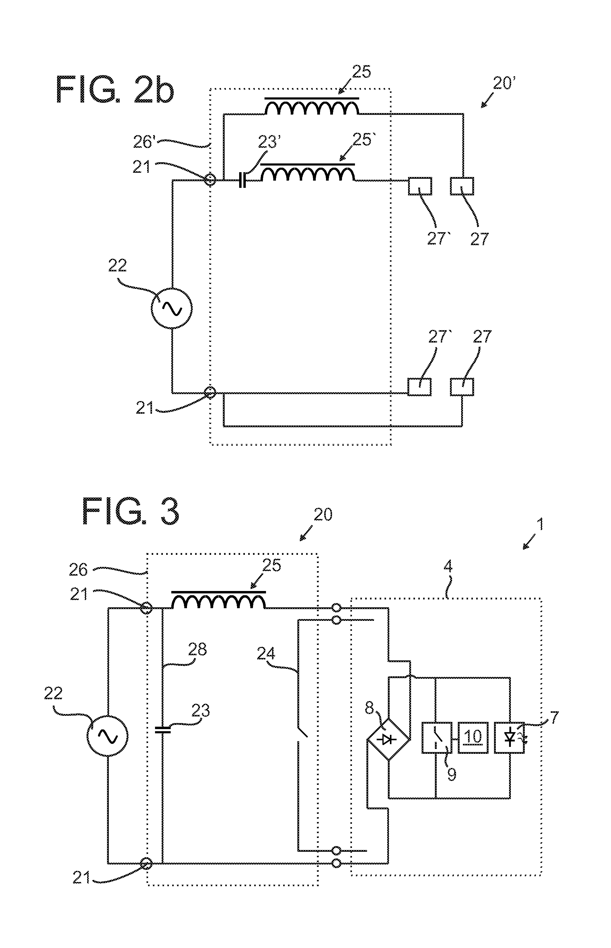
[0112]a typical fluorescent lamp fixture 20′ is shown in FIG. 2b in a schematic drawing. The lamp fixture 20′ is adapted to hold two lamps 1 and is accordingly equipped with a first pair of sockets 27 and a second pair of corresponding sockets 27′. The first pair of sockets 27 are connected with power over the series inductance 25, as discussed above. The second pair of sockets 27′ are connected with power in series with a further inductance 25′ and a series capacitor 23′. According to the present example, the capacitor 23′ is chosen with a sufficiently high capacitance so that the inductive power of both inductances 25, 25′ are compensated. Therefore, a dedicated PFC circuit 28, as shown in FIG. 2a, can be omitted with this circuit design.

[0113]The reactive ballast 26′ accordingly comprises an inductive branch, namely the circuit of inductance 25 and sockets 27, and a capacitive branch, i.e. the circuit of the capacitor 23′, the inductance 25′ and sockets 27′. While in the inductiv...

third embodiment

[0129]FIG. 8a shows lamp circuit 4″ in a schematic diagram. The embodiment of FIG. 8 substantially corresponds to the embodiment of FIG. 6 with the exception of feedback unit 60′ and a corresponding low voltage supply circuit 62′.

[0130]The low voltage supply circuit 62′ comprises a resistor 81 and an arrangement of two zener diodes 82. A low voltage supply for the feedback unit 60′ is coupled out via diode 83 and provides OP-amp 84 with operating power. Additionally, the voltage reference signal is generated from the arrangement of shunt voltage reference 85, e.g. TL341, resistor 93 and resistors 86, 87, which form a voltage divider. A capacitor 94 is provided as an energy buffer to smooth out the ripple in the low voltage supply.

[0131]The OP-amp 84 is connected with capacitor 88 to form an error integrator for the feedback control. The output of OP-amp 84 drives transistor 89, which draws a corresponding current from timing capacitor 49. Diode 95 inhibits current flow from the tran...

fourth embodiment

[0133]FIG. 8b shows the electric circuit 4′″ of an LED lamp 1. The embodiment of FIG. 8b substantially corresponds to the embodiment of FIG. 8a, with the exception of a simplified feedback unit 60″, which advantageously further reduces the overall cost of the LED lamp 1.

[0134]Different from FIG. 8, no operational amplifier is used to control the transistor 89 in the embodiment of FIG. 9. Instead an integration capacitor 97 is placed across the shunt voltage reference 85. The functionality of an error integrator and voltage reference are according to the present embodiment both provided by shunt voltage reference 85 and capacitor 97, which further simplifies the setup.


PUM


Abstract

The present invention relates to an LED lamp (1) adapted for operation with an alternating current. The LED retrofit lamp (1) comprises a LED unit (7, 7′, 7″, 7′″) and a compensation circuit with a controllable switching device (9, 9′), connected parallel to said LED unit (7, 7′, 7″, 7′″) to provide an alternate current path. A control unit (10, 10′, 10″) is adapted to control said switching device (9, 9′) in a compensation mode in which said switching device (9, 9′) is set to the conducting state for the duration of a shunt period in each half cycle of the alternating current to allow adapting the power/current of the inventive LED lamp (1), so that a versatile and optimized operation of the lamp (1) is possible.

Description

[0001]The invention relates to the field of lighting and particularly to an LED retrofit lamp adapted for operation with an alternating current.BACKGROUND OF THE INVENTION[0002]Recently, lighting devices have been developed utilizing light emitting diodes (LEDs) for a variety of lighting applications. Due to the increasing use of LEDs for lighting applications, LED lamps are developed to replace common incandescent or fluorescent lamps, i. e. for retrofit applications. In addition to an increase in the lifetime of such LED lamps in comparison to common lamps and thus lower cost, LED lamps typically contain less hazardous materials, so that recycling processes of such lamps can be conducted more efficiently.[0003]For the above mentioned retrofit applications, the LED lamp typically is adapted to fit the socket of the respective fixture to be retrofitted. Furthermore, since a maintenance of a lamp typically is conducted by a user, the LED lamp should be readily operational with any ty...

Claims


Application Information

Patent Timeline
Patent Type & Authority Applications(United States)
IPC IPC(8): H05B33/08H05B44/00
CPCH05B33/0809H05B33/0815Y02B20/383Y02B20/30H05B45/3725
Inventor DEPPE, CARSTENSAUERLANDER, GEORGRADERMACHER, HARALD JOSEF GUNTHERTAO, HAIMINJANS, WILLIAM PETER MECHTILDIS MARIE
Owner KONINKLIJKE PHILIPS ELECTRONICS NV
Why Eureka
Try Eureka