Optical component and method of manufacturing the same

a technology of optical components and optical components, applied in the field of optical components, can solve the problems of low reflection characteristic over the entire visible region, impact on the retina, deterioration of visibility, etc., and achieve the effect of improving visibility, adhesion, and effective antiglare

Active Publication Date: 2013-08-29
NIKON ESSILOR
View PDF4 Cites 58 Cited by
  • Summary
  • Abstract
  • Description
  • Claims
  • Application Information

AI Technical Summary

Benefits of technology

[0049]Furthermore, the inorganic multilayer film 3 is preferably designed to have a reflectivity of 1.5% or less over a wavelength region of 580 nm to 780 nm. Due to such a design, a spectacle lens which has a more effective antiglare effect and better visibility can be obtained.
[0050]In this embodiment, the high refractive index layer 7 is formed of a first layer 9 made of a high refractive index inorganic material which is provided close to the plastic base 2, a second layer 10 made of a low refractive index inorganic material which is provided on the first layer 9, and a third layer 11 made of a high refractive index inorganic material which is provided on the second layer 10.
[0051]The first layer 9 is provided to be brought into contact with the hard coating layer 6, and is made of zirconium dioxide (ZrO2) having a refractive index of 2.0. Other than ZrO2, for example, titanium dioxide (TiO2) and tantalum dioxide (Ta2O5) can be used as the high refractive index inorganic material constituting the first layer 9. Furthermore, the first layer 9 can also be made of oxide of an alloy of plural types including zirconium, titanium, and tantalum. In addition to these, for example, aluminum oxide (Al2O3), yttrium dioxide (Y2O3), hafnium dioxide (HfO2), and niobium dioxide (Nb2O5) can also be used.
[0052]Here, in this manner, when the first layer 9 is made of a high refractive index inorganic

Problems solved by technology

However, from recent studies, it is known that the low reflection characteristic over the entire visible region is not necessarily desirable for visibility and eye health.
In addition, regarding eye health, since the blue region (380 nm to 500 nm

Method used


Image

  • Optical component and method of manufacturing the same
  • Optical component and method of manufacturing the same
  • Optical component and method of manufacturing the same

Examples


first embodiment

(1) First Embodiment

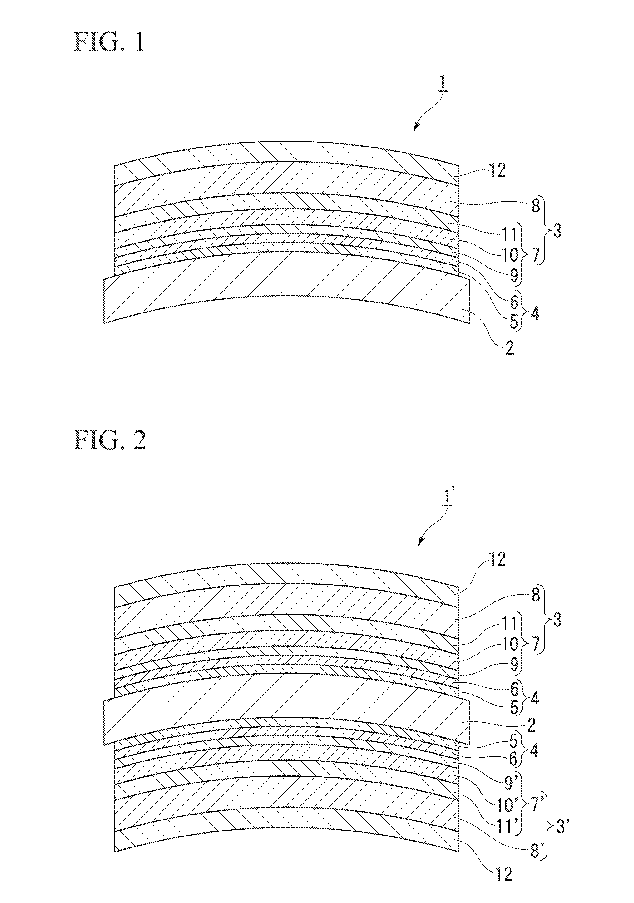
[0032]FIG. 1 is a sectional side view schematically showing an optical component of a first embodiment of the invention. The reference numeral 1 represents an optical component for a spectacle lens.

[0033]The optical component 1 is provided with a plastic base 2 and an inorganic multilayer film 3 disposed on a convex surface of the plastic base 2. In this embodiment, a functional thin film 4 is disposed between the convex surface of the plastic base 2 and the inorganic multilayer film 3. In this embodiment, the functional thin film 4 is formed of a primer layer 5 and a hard coating layer 6.

[0034]In the following description, the films 3 and 4, which are disposed on the surface (convex surface) of the plastic base 2, will mainly be described. However, actually, films which are the same as the films 3 and 4 formed on the surface (convex surface) are also formed on the rear surface (concave surface) of the plastic base 2.

[0035]The plastic base 2 is made of, for examp...

second embodiment

(2) Second Embodiment

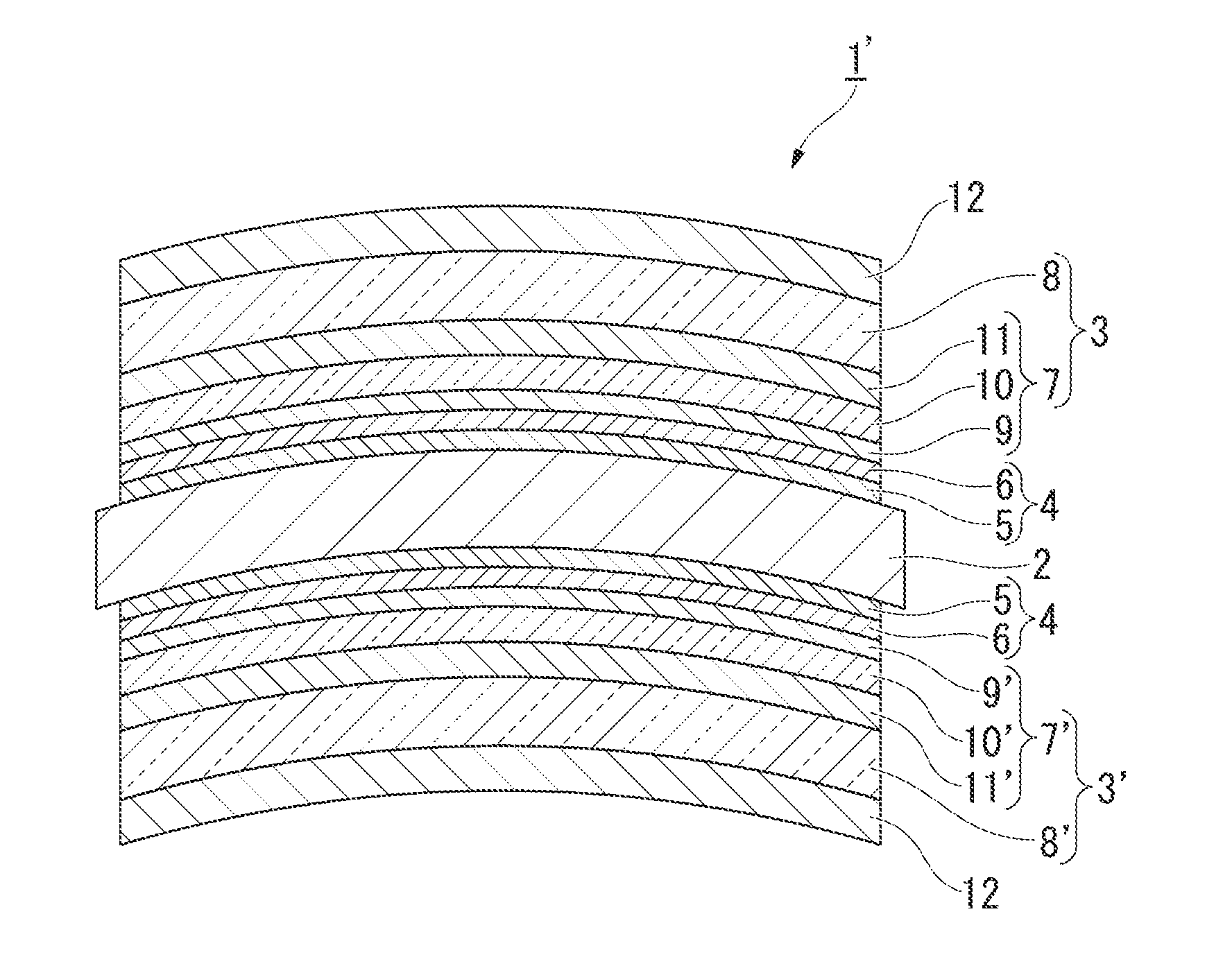
[0065]FIG. 2 is a sectional side view schematically showing an optical component of a second embodiment of the invention. The reference numeral 1′ represents an optical component for a spectacle lens. In FIG. 2, the same constituent elements as in the optical component 1 shown in FIG. 1 will be denoted by the same reference numerals, and descriptions thereof will be omitted.

[0066]The optical component 1′ is provided with, in addition to the structure of the optical component 1 of the first embodiment, an inorganic multilayer film 3′ disposed on a concave surface of a plastic base 2. In this embodiment, a functional thin film 4 is disposed between the concave surface of the plastic base 2 and the inorganic multilayer film 3′. The functional thin film 4 is formed of a primer layer 5 and a hard coating layer 6 in this embodiment.

[0067]The inorganic multilayer film 3′ has a double-layer configuration which has a high refractive index layer 7′ having a multilayer str...

examples

[0092]Hereinafter, examples of the embodiments of the invention will be described in more detail, but the invention is not limited to the following examples.

[0093]Test 1

[0094]On a urethane-based synthetic resin substrate, a silicon-based hard coating having a refractive index of 1.67 and a primer coating having a refractive index of 1.67 were prepared by thermal curing, and film formation was performed by a vacuum deposition method as follows.


PUM

PropertyMeasurementUnit
Fractionaaaaaaaaaa
Fractionaaaaaaaaaa
Fractionaaaaaaaaaa

Abstract

An optical component includes: a plastic base which has a convex surface and a concave surface; and a multilayer film which is disposed on at least the convex surface of the plastic base. The multilayer film has an average reflectivity of 2% to 10% over a wavelength range of 400 nm to 500 nm.

Description

CROSS-REFERENCE TO RELATED APPLICATION[0001]This is a continuation application of International Application No. PCT / JP2011 / 070856, filed on Sep. 13, 2011, which claims priority to Japanese Patent Application No. 2010-218711, filed Sep. 29, 2010, and Japanese Patent Application No. 2010-288319, filed Dec. 24, 2010, the contents of which are incorporated herein by reference.BACKGROUND[0002]1. Field of the Invention[0003]The present invention relates to an optical component and a method of manufacturing the optical component.[0004]2. Description of the Related Art[0005]In recent years, for spectacle lenses, plastic lenses have been used in many cases due to advantages such as lightweight, excellent impact resistance, and ease of dyeing. In the plastic lens for use in a spectacle lens, an antireflection film is generally provided on both sides of the plastic lens for the purpose of preventing surface reflection. Generally, the antireflection film for a spectacle lens has a low reflectio...

Claims


Application Information

Patent Timeline
IPC IPC(8): G02B1/11B05D5/06C23C14/24G02B1/10C23C14/22
CPCG02B1/113G02C7/02B05D5/06G02B1/11C23C14/24G02B1/105C23C14/221G02C7/104G02C7/105G02B1/18G02B1/14G02C7/00G02B5/22
Inventor TOMODA, MASAOKIITO, SATORUISHIMURA, KEIOKUMURA, HIROTATSU
Owner NIKON ESSILOR
Why Eureka
Try Eureka