Optical component and method of manufacturing the same

a technology of optical components and optical components, applied in the field of optical components, can solve the problems of low reflection characteristic over the entire visible region, impact on the retina, deterioration of visibility, etc., and achieve the effect of improving visibility, adhesion, and effective antiglare

Active Publication Date: 2019-08-06
NIKON ESSILOR
View PDF55 Cites 0 Cited by
  • Summary
  • Abstract
  • Description
  • Claims
  • Application Information

AI Technical Summary

Benefits of technology

[0049]In addition, in this embodiment, an inorganic multilayer film is used as a multilayer film. However, an organic multilayer film may be used as long as the advantageous effect of the invention is not impaired.
[0050]Furthermore, the inorganic multilayer film 3 is preferably designed to have a reflectivity of 1.5% or less over a wavelength region of 580 nm to 780 nm. Due to such a design, a spectacle lens which has a more effective antiglare effect and better visibility can be obtained.
[0051]In this embodiment, the high refractive index layer 7 is formed of a first layer 9 made of a high refractive index inorganic material which is provided close to the plastic base 2, a second layer 10 made of a low refractive index inorganic material which is provided on the first layer 9, and a third layer 11 made of a high refractive index inorganic material which is provided on the second layer 10.
[0052]The first layer 9 is provided to be brought into contact with the hard coating layer 6, and is made of zirconium dioxide (ZrO2) having a refractive index of 2.0. Other than ZrO2, for example, titanium dioxide (TiO2) and tantalum dioxide (Ta2O5) can be used as the high refractive index inorganic material constituting the first layer 9. Furthermore, the first layer 9 can also be made of oxide of an alloy of plural types including zirconium, titanium, and tantalum. In addition to these, for example, aluminum oxide (Al2O3), yttrium dioxide (Y2O3), hafnium dioxide (HfO2), and niobium dioxide (Nb2O5) can also be used.
[0053]Here, in this manner, when the first layer 9 is made of a high refractive index inorganic material (ZrO2), the adhesion between the first layer 9 and the hard coating layer 6 can be obtained. That is, this is because the adhesion (adhesion power) between the layer (ZrO2) made of a high refractive index inorganic material and the hard coating layer 6 is greater than the adhesion (adhesion power) between the layer (SiO2) made of a low refractive index inorganic material and the hard coating layer 6. In addition, even when the functional thin film 4 (primer layer 5 and hard coating layer 6) is omitted, the adhesion (adhesion power) between the high refractive index layer (ZrO2) and the plastic base 2 is greater than the adhesion (adhesion power) between the low refractive index layer (SiO2) and the plastic base 2, and thus using a high refractive index inorganic material is better for adhesion.
[0054]The second layer 10 is provided to be brought into contact with the first layer 9, and is made of silicon dioxide (SiO2) having a refractive index of 1.47. Other than SiO2, for example, MgF2 having a refractive index of 1.36 can be used as the low refractive index inorganic material constituting the second layer 10.

Problems solved by technology

However, from recent studies, it is known that the low reflection characteristic over the entire visible region is not necessarily desirable for visibility and eye health.
In addition, regarding eye health, since the blue region (380 nm to 500 nm) of visible light has a high intensity of energy, it is said to be a cause of impact to the retina and the like.
However, in the dyed lens, the entire visible region is cut, and thus visibility deteriorates due to a reduction in light intensity.

Method used


Image

  • Optical component and method of manufacturing the same
  • Optical component and method of manufacturing the same
  • Optical component and method of manufacturing the same

Examples


examples

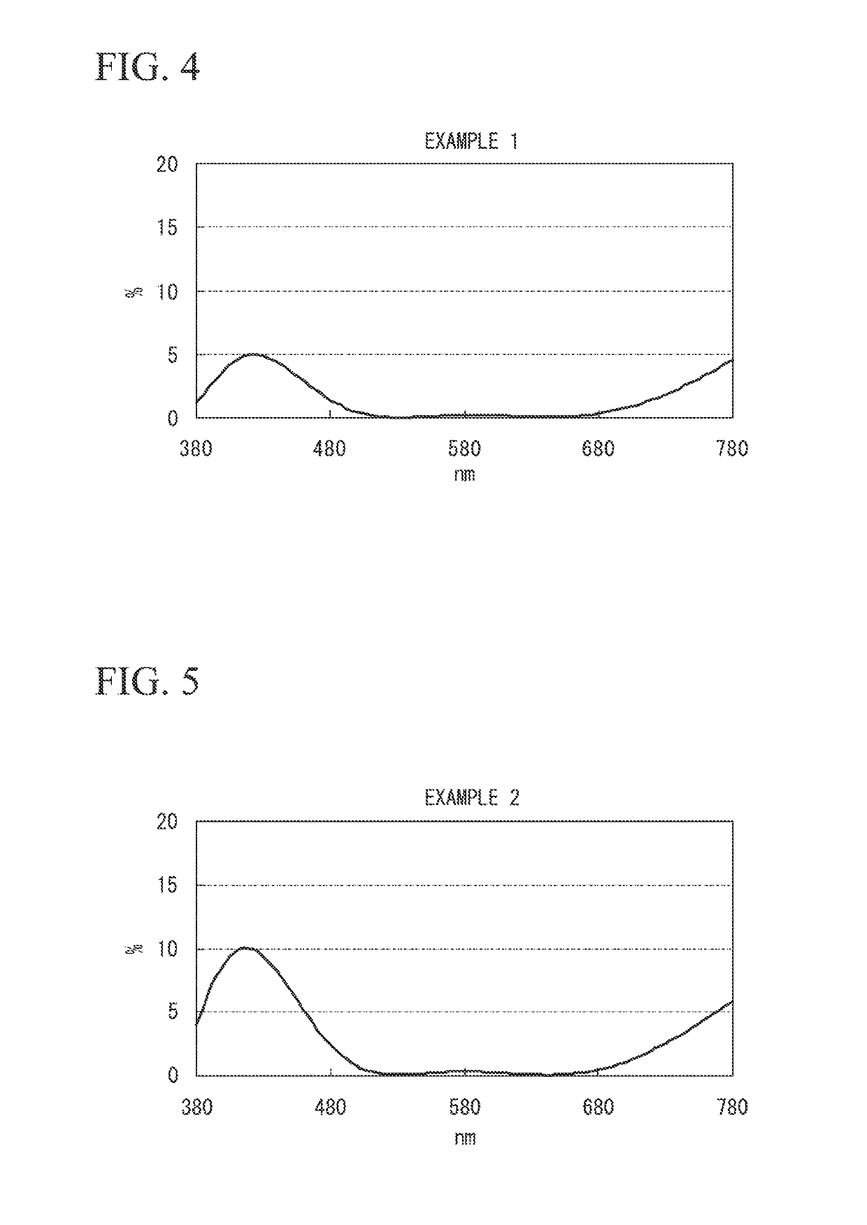
[0100]Hereinafter, examples of the embodiments of the invention will be described in more detail, but the invention is not limited to the following examples.

[0101]Test 1

[0102]On a urethane-based synthetic resin substrate, a silicon-based hard coating having a refractive index of 1.67 and a primer coating having a refractive index of 1.67 were prepared by thermal curing, and film formation was performed by a vacuum deposition method as follows.

example 1

[0103]Convex Surface: A lens was set in a rotating dome provided in a vacuum chamber, the temperature in the vacuum chamber was adjusted to 70 degrees Celsius by heating, air was exhausted until the pressure was adjusted to 1.0×10⁻³ Pa, and Ar ion beam cleaning was carried out for 60 seconds under conditions of an acceleration voltage of 500 V and an acceleration current of 100 mA. Then, a first layer ZrO2 (refractive index 2.00) having an optical film thickness of 0.035λ, a second layer SiO2 (refractive index 1.47) having an optical film thickness of 0.565λ, a third layer ZrO2 (refractive index 2.00) having an optical film thickness of 0.075λ, a fourth layer SiO2 (refractive index 1.47) having an optical film thickness of 0.04λ, a fifth layer ZrO2 (refractive index 2.00) having an optical film thickness of 0.32λ, and a sixth layer SiO2 (refractive index 1.47) having an optical film thickness of 0.26λ, were sequentially applied from the plastic base side. λ is 500 nm in terms of cen...

example 3

[0109]Convex Surface: A lens was set in a rotating dome provided in a vacuum chamber, the temperature in the vacuum chamber was adjusted to 70 degrees Celsius by heating, air was exhausted until the pressure was adjusted to 1.0×10⁻³ Pa, and ion beam cleaning was carried out for 60 seconds under conditions of an acceleration voltage of 500 V and an acceleration current of 100 mA. Then, a first layer ZrO2 (refractive index 2.00) having an optical film thickness of 0.095λ, a second layer SiO2 (refractive index 1.47) having an optical film thickness of 0.595λ, a third layer ZrO2 (refractive index 2.00) having an optical film thickness of 0.05λ, a fourth layer SiO2 (refractive index 1.47) having an optical film thickness of 0.03λ, a fifth layer ZrO2 (refractive index 2.00) having an optical film thickness of 0.305λ, and a sixth layer SiO2 (refractive index 1.47) having an optical film thickness of 0.275λ were sequentially applied from the plastic base side. λ is 500 nm in terms of center...


PUM

PropertyMeasurementUnit
reflectivityaaaaaaaaaa
wavelengthaaaaaaaaaa
reflectivityaaaaaaaaaa

Abstract

An optical component includes: a plastic base which has a convex surface and a concave surface; and a multilayer film which is disposed on at least the convex surface of the plastic base. The multilayer film has an average reflectivity of 2% to 10% over a wavelength range of 400 nm to 500 nm.

Description

CROSS-REFERENCE TO RELATED APPLICATION[0001]This is a continuation application of International Application No. PCT / JP2011 / 070856, filed on Sep. 13, 2011, which claims priority to Japanese Patent Application No. 2010-218711, filed Sep. 29, 2010, and Japanese Patent Application No. 2010-288319, filed Dec. 24, 2010, the contents of which are incorporated herein by reference.BACKGROUND[0002]Field of the Invention[0003]The present invention relates to an optical component and a method of manufacturing the optical component.[0004]Description of the Related Art[0005]In recent years, for spectacle lenses, plastic lenses have been used in many cases due to advantages such as lightweight, excellent impact resistance, and ease of dyeing. In the plastic lens for use in a spectacle lens, an antireflection film is generally provided on both sides of the plastic lens for the purpose of preventing surface reflection. Generally, the antireflection film for a spectacle lens has a low reflection char...

Claims


Application Information

Patent Timeline
Patent Type & Authority Patents(United States)
IPC IPC(8): G02B1/18G02B23/16G02B1/11C23C14/24G02B1/10G02C7/10G02B1/113B05D5/06C23C14/22G02B1/14
CPCG02B1/11B05D5/06C23C14/221C23C14/24G02B1/18G02C7/104G02C7/105G02B1/113G02B1/14G02B1/105G02B5/22G02C7/00G02C7/02
Inventor TOMODA, MASAOKIITO, SATORUISHIMURA, KEIOKUMURA, HIROTATSU
Owner NIKON ESSILOR
Why Eureka
Try Eureka