
Shut-off member of a pressure reducing valve of a pressure regulator device, and pressure regulator device having such shut-off member

Inactive Publication Date: 2013-09-05
MARES
View PDF5 Cites 7 Cited by
  • Summary
  • Abstract
  • Description
  • Claims
  • Application Information

AI Technical Summary

Benefits of technology

The present invention provides a piston shut-off member with a coated head and a wider shaft, which is made of elastomeric material and coated with at least one layer of elastomeric material. The coated head cooperates with a seat of a pressure reducing valve and perfectly seals it without any risk of peeling off or removal of the elastomeric layer. The shaft can cooperate with the seal element, such as an O-ring, at the opening through which the shaft slides in a high-pressure chamber without deformation and alteration of the materials that form the shaft and O-ring. The elastomeric coating prevents microbubble penetration between the cap and the coating and acts as friction and interlocking fit of the cap on the shut-off member. The elastomeric coating is adapted to ensure resistance to pressure against the valve seat and prevents leakage problems at the base of the shaft. The sealing action is ensured by contact between a soft surface and a hard surface, which prevents deformation and alteration of the materials and prevents contact of two soft materials.

Problems solved by technology

Particularly, if the coating material for the head and the shaft is too soft, it will be prone to deformation on the shaft where cooperation with the O-ring occurs, resulting in increased friction during the movement of the shut-off member and in delayed closing / opening of the valve seat.
Conversely, if the coating material is too rigid, an imperfect seal may be obtained when the head of the shut-off member abuts against the valve seat.
In order to obviate the problem of plastic deformation on the shaft where cooperation with the O-ring occurs, resulting in increased friction during the movement of the shut-off member, as well as delayed closing / opening of the valve seat, and eventually inappropriate operation of the pressure regulator device, U.S. Pat. No. 7,341,073 provides a coating for the shut-off member that is composed of two plastic layers, where the head of the shut-off member is overcoated with a second layer of a plastic material that is softer than the first layer of plastic material that coats the shaft and head of the shut-off member.
Nevertheless, this technical arrangement adds complexity to fabrication of the shut-off member, as it requires molding of two layers of chemically different materials, one above the other.
Particularly, since the shut-off member of U.S. Pat. No. 7,341,073 is required to be coated by two plastic coating layers that must be compatible with each other, this chemical compatibility between the rigid and less rigid layers will restrict the selectable materials.
Therefore, the plastic layer that covers the shaft end opposite to the head, may be deformed or altered by contact with the seal element, which is designed to seal the high-pressure chamber at the hole through which said shaft end slides, resulting in increased friction during operation and / or gas leakage at said seal.
In further prior art technical arrangements, plastic overmolding is only provided at the head part of the shut-off member, using an adhesive layer to improve adhesion between the plastic layer (coated over a small area) and the metal that forms the body of the shut-off member, thereby limiting penetration of gas microbubbles between the layers of different natures.
This is required because the head of the shut-off member, namely the junction between the head and the shaft is exposed to high pressure and the plastic coating and the metal of the shut-off member are chemically incompatible.
Nevertheless, these arrangements increase the complexity and costs for fabricating the shut-off member (as they require a combination of a metal washer and an adhesive layer for holding the plastic coating of the head in position) and do not prevent gas microbubbles in the high-pressure chamber from penetrating between the metal of the shut-off member and the plastic material, thereby causing the coating to be peeled off, and resulting in inadequate operation of the pressure regulator device.
The drawback of this type of shut-off members is that rubber can be easily cut, and cause inadequate operation of the pressure reducing valve.
Furthermore, due to the small rubber / metal contact area in the shut-off member, the rubber part may be easily peeled off, possibly due to penetration of gas microbubbles between the pad and the metal head.

Method used


Image

  • Shut-off member of a pressure reducing valve of a pressure regulator device, and pressure regulator device having such shut-off member
  • Shut-off member of a pressure reducing valve of a pressure regulator device, and pressure regulator device having such shut-off member
  • Shut-off member of a pressure reducing valve of a pressure regulator device, and pressure regulator device having such shut-off member

Examples


Embodiment Construction

[0072]Detailed descriptions of embodiments of the invention are provided herein. It is to be understood, however, that the present invention may be embodied in various forms. Therefore, the specific details disclosed herein are not to be interpreted as limiting, but rather as a representative basis for teaching one skilled in the art how to employ the present invention in virtually any detailed system, structure, or manner.

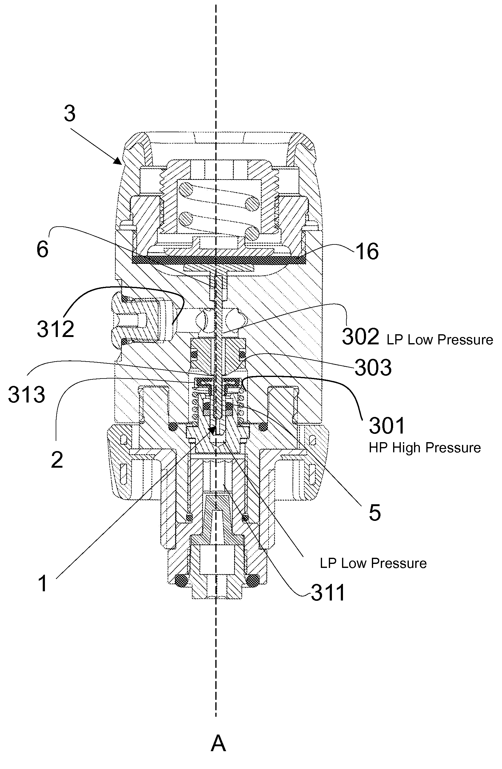
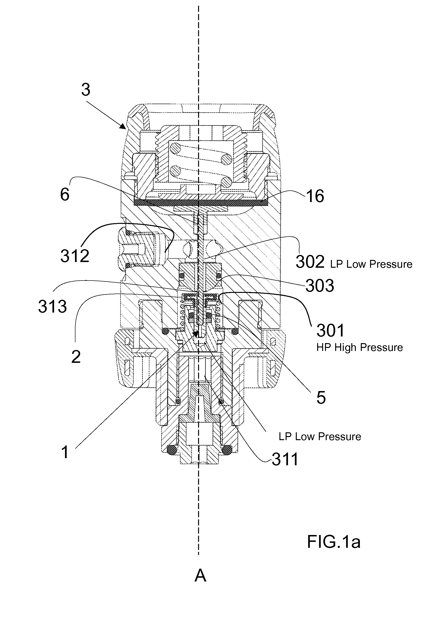
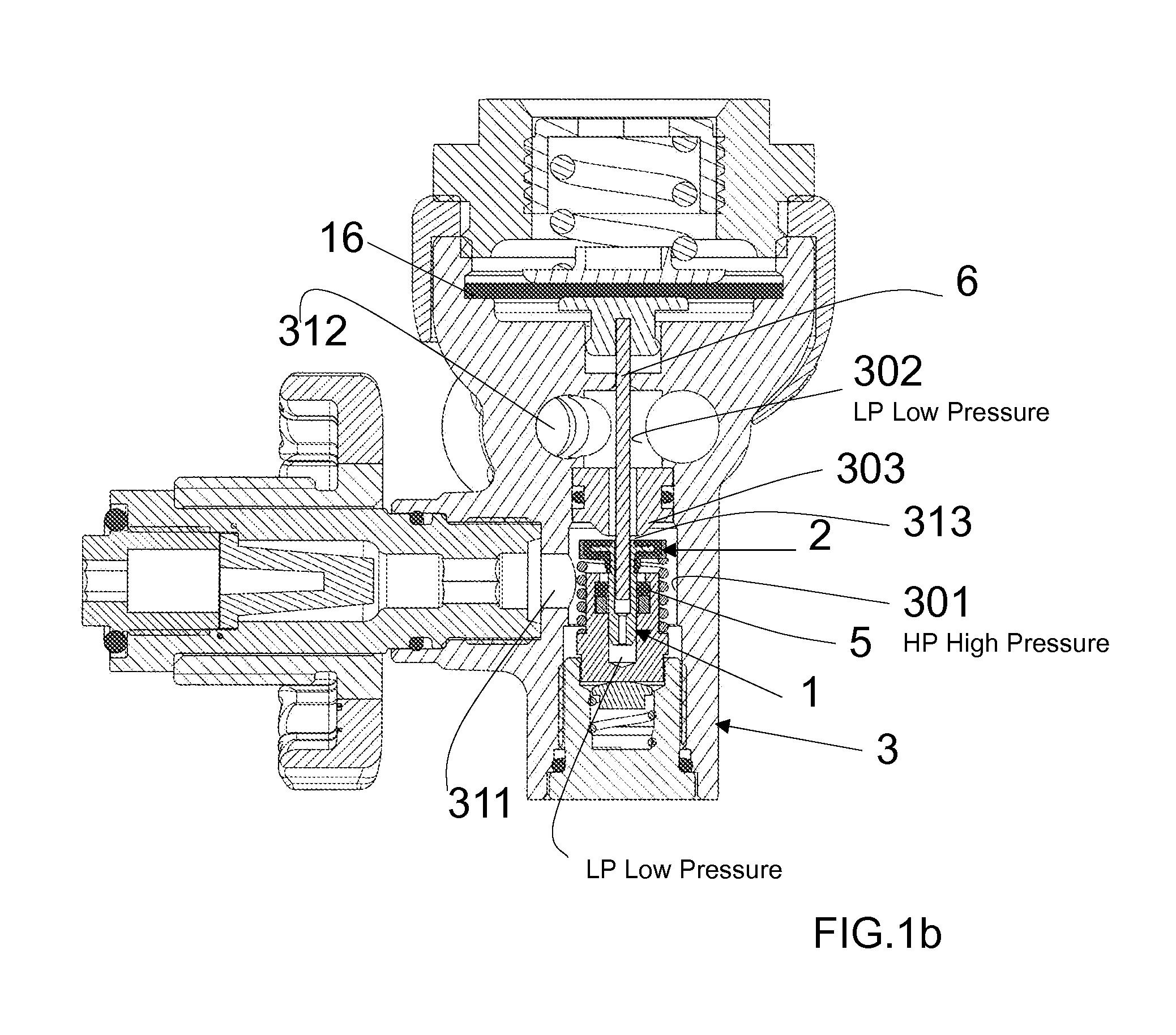
[0073]Referring to FIGS. 1a, 1b, 1c and1d, the pressure regulator device 3 has a main body divided into at least one high-pressure chamber 301 having a high-pressure gas inlet 311 and a chamber at lower pressure, so-called low-pressure chamber 302, having a lower-pressure gas inlet 312.

[0074]The high-pressure chamber 301 is separated from the low-pressure chamber 302 by a valve seat 313 formed on the separator element 303 for separating said high-pressure chamber 301 from said low-pressure chamber 302, said seat 313 cooperating with a piston shut-off member 1 movi...


PUM


Abstract

A shut-off member of a pressure reducing valve of a pressure regulator device, such as a diaphragm-type first stage for scuba diving, includes an enlarged head connected to a shaft and cooperating with a valve seat that separates a chamber supplied with high pressure gas from a chamber in which gas is at a lower pressure. The enlarged head and an end section of predetermined length of the shaft, connected to the enlarged head, are seamlessly coated with at least one layer of elastomeric material. Such coating of elastomeric material is limited to an end portion of the shaft connected to the enlarged head and the coated shaft portion is entirely contained in the high-pressure chamber in any operating position of the shut-off member.

Description

FIELD OF THE INVENTION[0001]The present invention relates to a shut-off member of a pressure reducing valve of a pressure regulator device, and pressure regulator device having such shut-off member.BACKGROUND OF THE INVENTION[0002]Air supply and pressure regulator devices are known, for instance for use in scuba diving, and generally have a double stage, where the first pressure reducing stage is connected to a high-pressure source of breathable gas, such as a tank filled to a pressure of 200-300 bar, and is designed to reduce said pressure to a predetermined intermediate pressure.[0003]Generally, such first pressure reducing state includes a body having an inlet connected to a high-pressure source of breathable gas and an outlet for the breathable gas at a reduced pressure as compared with the inlet gas pressure. Said body is divided into at least one high-pressure gas chamber, communicating with said inlet, and a low-pressure gas chamber, connected with said outlet, said low-press...

Claims


Application Information

Patent Timeline
IPC IPC(8): F16K5/08
CPCB63C11/2209F16K1/36F16K5/08B63C11/22G05D16/0666A62B9/022Y10T137/7823
Inventor NOCETI, DANTE
Owner MARES
Features
  • Generate Ideas
  • Intellectual Property
  • Life Sciences
  • Materials
  • Tech Scout
  • Unparalleled Data Quality
  • Higher Quality Content
  • 60% Fewer Hallucinations
Learn More