Resilient seal having a pressurized bellows spring

a bellows spring and seal technology, applied in the field of resilient seals, can solve the problems of leakage, high cycle fatigue of seals, and increase sealing requirements, and achieve the effect of increasing seal force and increasing temperatur

Inactive Publication Date: 2013-09-05
EATON CORP
View PDF9 Cites 6 Cited by
  • Summary
  • Abstract
  • Description
  • Claims
  • Application Information

AI Technical Summary

Benefits of technology

[0004]The exemplary resilient seal and seal assembly uses a bellows spring that includes a sealed internal chamber having a volume that is filled with a gas, such as an inert gas, which generates an increasing seal force with increasing temperature to ensure that the seal assembly tracks the cavity surfaces, or face plates, as they move, preventing a gap from forming. The bellows spring is formed by a plurality of specially designed walls that are welded together in a chamber pressurized with a gas, such as an inert gas. This trapped gas provides the increasing spring force at higher temperatures to offset the losses in the mechanical spring or to allow the mechanical spring to be designed for a lower stress state at the position where the assembly spends the majority of time.

Problems solved by technology

If the seal breaks contact with the component surfaces, leakage can occur.
Additionally, a gap can prevent external pressure energization of the seal if so designed, and can allow airflow induced flutter of the seal leading to high cycle fatigue of the seal.
As performance expectations for gas turbine engines increase, sealing requirements increase as well while engine internal operating conditions become more severe.
Typically used Nickel-Chromium alloys maintain useful mechanical properties over a wide range of engine operating conditions, but become less suitable for resilient metallic seals above 1200 degrees F. Various alloys with improved stress relaxation or oxidation resistance properties have been employed in certain applications; however, these alloys typically lack the mechanical properties to ensure the sealing functionality expected.

Method used


Image

  • Resilient seal having a pressurized bellows spring
  • Resilient seal having a pressurized bellows spring
  • Resilient seal having a pressurized bellows spring

Examples


Embodiment Construction

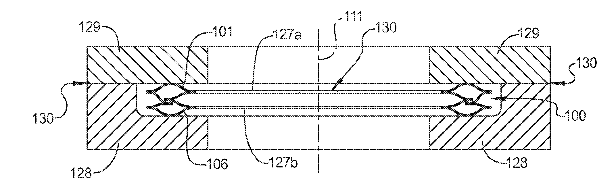
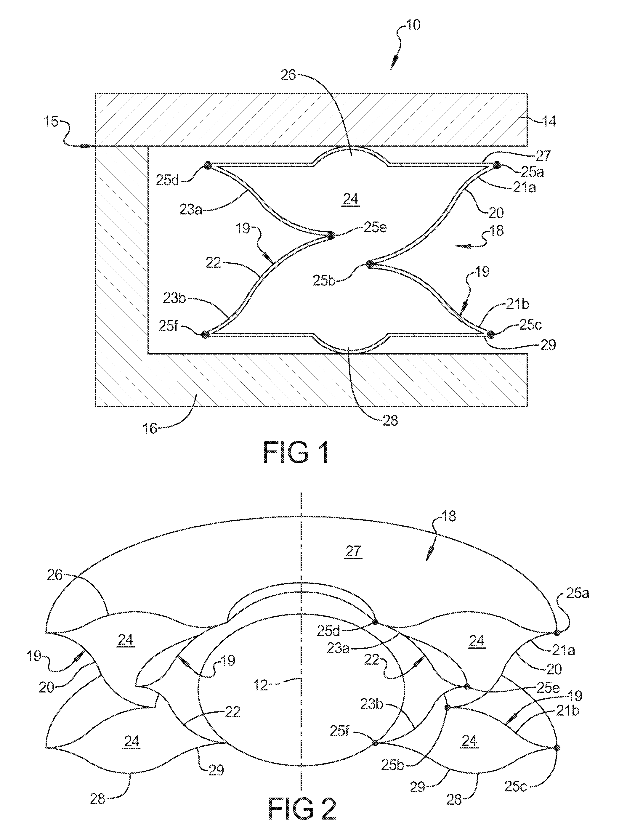
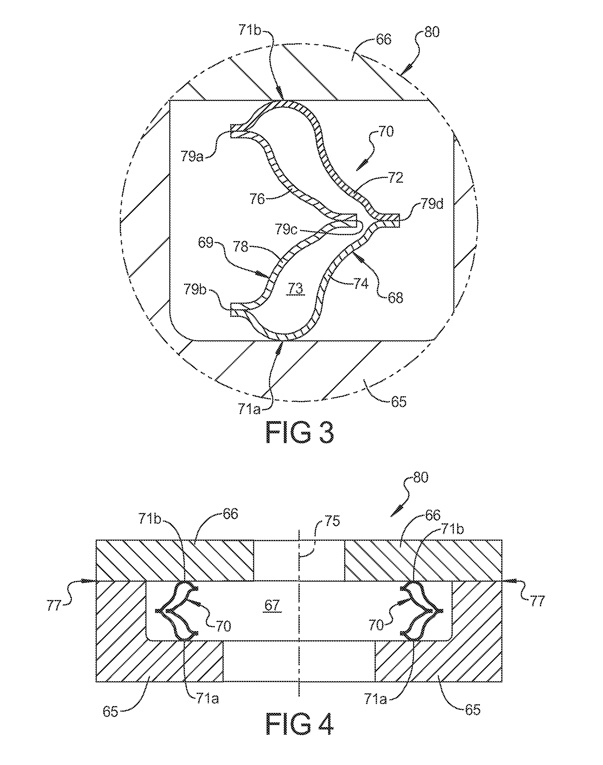
[0019]Referring now to the discussion that follows and also to the drawings, illustrative approaches to the disclosed systems and methods are shown in detail. Although the drawings represent some possible approaches, the drawings are not necessarily to scale and certain features may be exaggerated, removed, or partially sectioned to better illustrate and explain the present disclosure. Further, the descriptions set forth herein are not intended to be exhaustive or otherwise limit or restrict the claims to the precise forms and configurations shown in the drawings and disclosed in the following detailed description.

[0020]In this disclosure, certain terminology will be used in the following description for convenience in reference only and will not be limiting. The terms “rightward” and “leftward” will refer to directions in the drawings in connection with which the terminology is used. The terms “inwardly” and “outwardly” will refer to directions toward and away from, respectively, t...


PUM

PropertyMeasurementUnit
sealing forceaaaaaaaaaa
physical propertiesaaaaaaaaaa
thicknessaaaaaaaaaa

Abstract

An increased resilience seal utilizing a sealed gas filled inner chamber in a bellows spring that functions as both a mechanical spring and a gas spring to provide a more constant level of separation force between two face plates to provide a seal between two mechanical components such as those found in an aircraft jet engine. The bellows spring is made of a plurality of walls that are joined together in a pressurized chamber that is filled with a gas, such as an inert gas. In alternative embodiments, the bellows spring is made of walls that are shaped and oriented to optimize the operating characteristics of the bellows spring when the pressure is increased in a sealed inner chamber in response to elevated temperature. In one embodiment, the walls forming a portion of the chamber overlap to optimize the geometry of the bellows spring.

Description

TECHNICAL FIELD[0001]What is disclosed is a resilient seal for use in high temperature applications such as a jet turbine engine and more specifically, a resilient metallic axial face seal for use in semi-static high temperature applications such as between components in a jet turbine engine, which generates a mechanical spring force and a gas spring force to supplement the mechanical spring force to create a sealing contact force between the seal and face plates.PRIOR ART[0002]In the prior art, the housing face plates of an axial face seal assembly are separated and sealed by a formed metallic spring. The quality of the seal depends on the physical properties of the spring to provide a separation force between engine components, such as face plates to try to ensure that a gas seal is created to seal a separation gap between the engine components. This type of seal is commonly used in gas turbine engines to provide a gas seal between certain components, such as engine core sections ...

Claims


Application Information

Patent Timeline
Patent Type & Authority Applications(United States)
IPC IPC(8): F16J15/52B23P11/00
CPCY10T29/49826F16J15/0893
Inventor SWENSEN, JEFFREY E.ROACH, MATTHEW E.
Owner EATON CORP
Why Eureka
Try Eureka