Energy generation system and method thereof

a technology of energy generation system and energy generation method, which is applied in the direction of machines/engines, mechanical equipment, transportation and packaging, etc., can solve the problem of capture of greenhouse gases produced during the combustion of fuels

Active Publication Date: 2013-09-05
YEDA RES & DEV CO LTD
View PDF7 Cites 19 Cited by
  • Summary
  • Abstract
  • Description
  • Claims
  • Application Information

AI Technical Summary

Problems solved by technology

One of the challenging problems facing the power generation industry is the capture of greenhouse gases produced during the combustion of fuels.
More spec

Method used


Image

  • Energy generation system and method thereof
  • Energy generation system and method thereof
  • Energy generation system and method thereof

Examples


Embodiment Construction

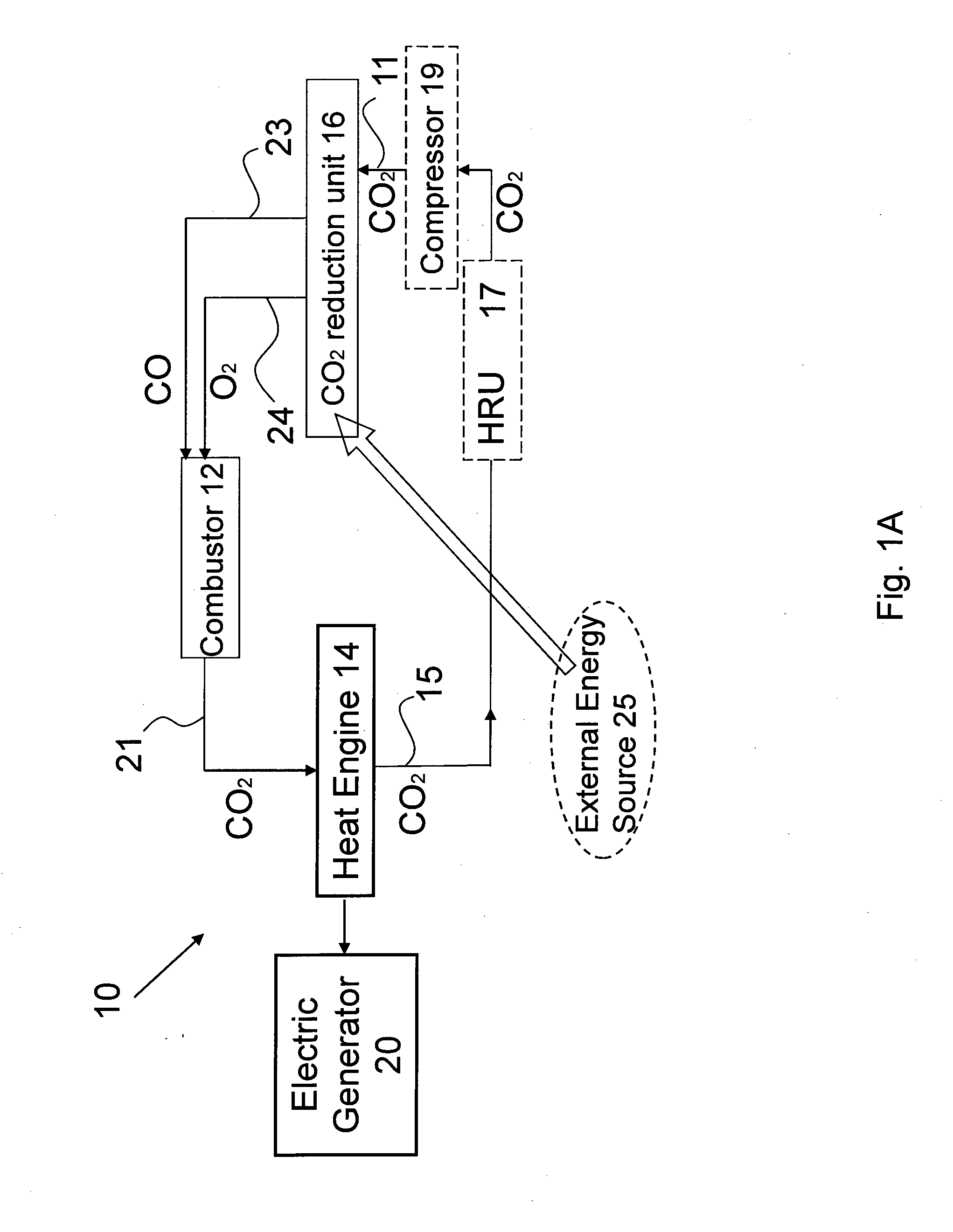
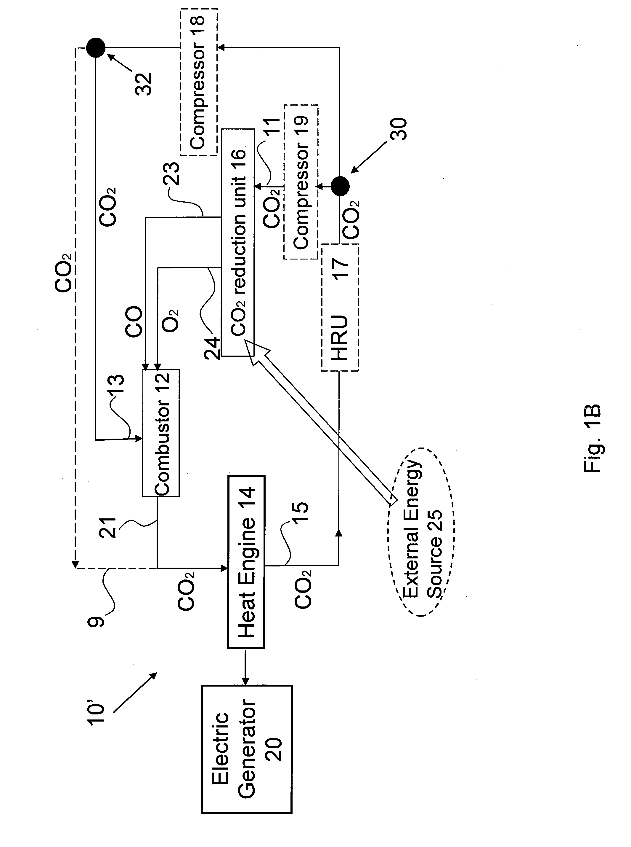
[0072]Reference is made to FIG. 1A illustrating a general block diagram of an energy generation system 10 of the present invention. The system 10 is configured to operate a heat engine 14, and comprises a CO2 reduction unit 16 energized by an external energy source 25 (e.g. solar or nuclear energy), and a combustor 12. The reduction unit 16 is configured for reducing CO2 to CO and O2, and includes a gas inlet 11 for inputting CO2, a CO gas outlet 23, and an O2 gas outlet 24. The combustor 12 is configured for effecting an oxy-fuel combustion of CO, and has gas inlets connected to the outlets 23 and 24 of the CO2 reduction unit 16 for receiving the CO and O2 gases, and a gas (CO2) outlet 21 connectable to a gas inlet of the heat engine 14. The CO2 leaving the combustor 12 has a certain heat because of the exothermal combustion of CO. Such heated CO2 is introduced into the heat engine 14, where the heat is converted into work, for example in the form of rotational mechanical energy. C...


PUM


Abstract

An energy generation system and method are presented for use in operating a heat engine. The energy generation method comprises: reducing a CO2 gas into CO and O2 gases; reacting said CO and O2 gases, thus combusting the CO gas, and yielding a substantially pure CO2 outlet gas; and supplying said CO2 outlet gas to the heat engine as a working gas in its heat-to-work generation process.

Description

FIELD OF THE INVENTION[0001]This invention generally relates to an energy generation system and method thereof by using clean fuel combustion.BACKGROUND OF THE INVENTION[0002]One of the challenging problems facing the power generation industry is the capture of greenhouse gases produced during the combustion of fuels. More specifically, the main challenge is the capture of Carbon Dioxide (CO2), since this molecular structure is the major greenhouse gas emitted during combustion.[0003]Several technologies exist for the capture of CO2. They are generally divided into the following groups: post combustion capture, oxy-fuel combustion, and pre-combustion capture.GENERAL DESCRIPTION[0004]In post combustion capture, the CO2 is separated from the flue gas after the combustion of a fuel. This can be done in several ways, but the most common and mature technology utilizes chemical absorption by amines including primary amines such as monoethanol amine (MEA), diglycolamine (DGA); secondary am...

Claims


Application Information

Patent Timeline
IPC IPC(8): F01K23/10H02K7/18F02C3/34F02C1/00F02C3/22
CPCF02C3/20F02C3/22F02C3/34Y02E10/46F01K23/10F02C1/00H02K7/18Y02E20/16F02C1/10
Inventor KARNI, JACOBGARBI, URI
Owner YEDA RES & DEV CO LTD
Why Eureka
Try Eureka