Gradient coil with correction windings and method for production thereof

a gradient coil and correction winding technology, applied in the field of active shielded gradient coil system, can solve the problems of complex nmr experiment, long waiting time for the experiment, and the inability to recover an nmr signal

Active Publication Date: 2013-09-05
BRUKER SWITZERLAND AG
View PDF3 Cites 12 Cited by
  • Summary
  • Abstract
  • Description
  • Claims
  • Application Information

AI Technical Summary

Benefits of technology

[0046]The following is a brief description of the negative effects of the eddy currents on the NMR signal.
[0047]In accordance with the Larmor theorem, the movement of the magnetization vector {right arrow over (M)} of an atomic nucleus in a static magnetic field {right arrow over (B)} corresponds to a precession about the {right arrow over (B)} axis with the Larmor frequency {right arrow over (ω)}=−γ·{right arrow over (B)}. The coefficient γ is called gyromagnetic ratio and is an isotope-specific constant. The following applies e.g. for 1H nuclei γ=2.675×10⁸ T−1s−1.
[0048]Let Mz be the equilibrium magnetization in the measuring volume. Mz is oriented parallel to the main magnetic field {right arrow over (B)}0 in the z direc

Problems solved by technology

Recovery of an NMR signal may sometimes take a long time, which can represent a great obstacle for complex NMR experiments.
This waiting time is disadvantageous for the experiment since the magnetization decreases through relaxation processes.
For larger molecules, such as e.g. proteins, the relaxation times are short and for this reason waiting times have a particularly disadvantageous effect.
Conversely, the quality of the results of such an experiment may strongly suffer from the artefacts which are generated by eddy currents induced by gradients in case these waiting times are not sufficiently long.
The distortions of the signal, which are generated by eddy currents, are one of the greatest obstacles of this method.
The problem of eddy currents induced by gradients has always been a major issue in high-resolution NMR spectroscopy.
The negative effects of the eddy currents on the quality of the spectra have greatly limited the application of field gradient NMR for a long time.
These two types of ineffective conductors can be installed everywhere.
the high conductivity of these structures results

Method used


Image

  • Gradient coil with correction windings and method for production thereof
  • Gradient coil with correction windings and method for production thereof
  • Gradient coil with correction windings and method for production thereof

Examples


Embodiment Construction

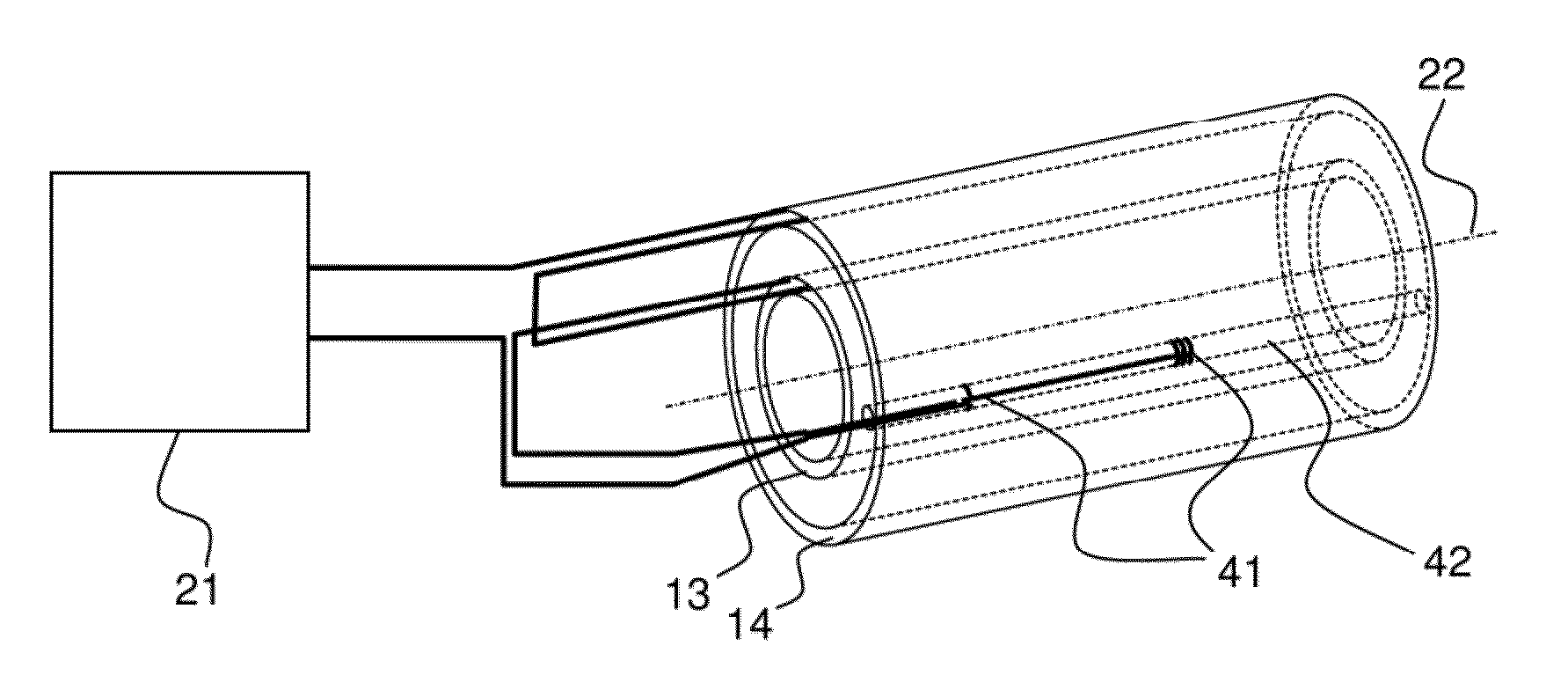
[0121]The magnetic residual fields of the gradient coil system on the cylinder tube with radius c are described below by the vector potentials on the cylinder surface c.

[0122]Let {right arrow over (A)}Soll,c be the desired vector potential that is generated due to the non-vanishing external residual fields. Since these are external residual fields c>b applies (wherein b is the outer radius of the shielding coil). {right arrow over (A)}Soll,c is determined in the design of the gradient coil system and is generated by discretization of the currents both in the main coil and also in the shielding coil and by the limited space in the z direction. This vector potential is already optimized with respect to the effects of the induced eddy currents, which flow on the cylinder tube after switching the current in the gradient coil system, on the NMR signal. For an actual coil arrangement of one single gradient coil, let {right arrow over (A)}Ist,c be the actual vector potential on the same cy...


PUM

PropertyMeasurementUnit
Angleaaaaaaaaaa
Massaaaaaaaaaa
Angleaaaaaaaaaa

Abstract

In a coil arrangement for nuclear magnetic resonance comprising a main coil (13), a shielding coil (14), and at least one correction coil (41), the function of which consists in forming a magnetic field gradient with eddy current properties which are as good as possible, the main coil (13) and the shielding coil (14) are electrically connected in series with the correction coil (41). The deviations of the residual field from the desired design generated by production tolerances are thereby modified by the correction coil in such a fashion that the long-lasting eddy currents are suppressed. This either reduces the waiting time that must lapse after a gradient pulse before a predetermined field homogeneity is achieved or e.g. the deviations from the desired field are minimized in imaging applications.

Description

[0001]This application claims Paris convention priority of DE 10 2012 203 343.2 filed Mar. 2, 2012, the entire disclosure of which is hereby incorporated by reference.BACKGROUND OF THE INVENTION[0002]The invention concerns an actively shielded gradient coil system for use in a magnetic resonance device, comprising a main field magnet which generates a main magnetic field that is oriented in the direction of a z-axis, wherein, when a current flows, the gradient coil system generates a gradient field in a measuring volume through which the z-axis extends, wherein the gradient coil system comprises a main coil, a shielding coil and at least one correction coil, wherein the active conductor elements of the main coil and of the shielding coil, which contribute to the gradient field when a current flows, each take up spatial areas in a plane perpendicular to the z-axis, wherein the partial area taken up by the main coil extends in a radial direction with respect to the z-axis from r_min_1...

Claims


Application Information

Patent Timeline
IPC IPC(8): G01R33/385
CPCG01R33/4215G01R33/56518Y10T29/49004G01R33/3858G01R33/385
Inventor DENOTH, SCHIMUNBUTTAZZONI, SILVIASPECK, THOMASWILHELM, DIRK
Owner BRUKER SWITZERLAND AG
Why Eureka
Try Eureka