Optical information recording medium

a technology of optical information and recording medium, which is applied in the field of optical information recording medium, can solve the problems of insufficient recording sensitivity and insufficient reception of energy, and achieve the effects of increasing the number of recording layers, increasing storage capacity, and reading information easily

Active Publication Date: 2013-09-05
FUJIFILM CORP
View PDF6 Cites 9 Cited by
  • Summary
  • Abstract
  • Description
  • Claims
  • Application Information

AI Technical Summary

Benefits of technology

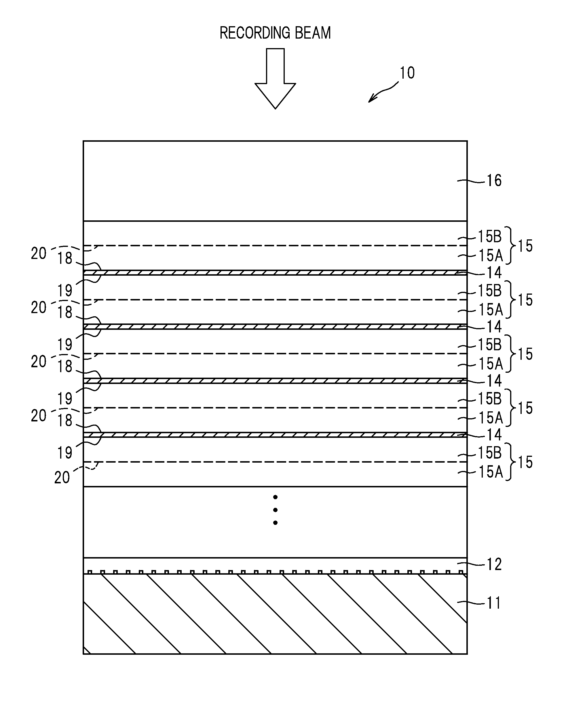
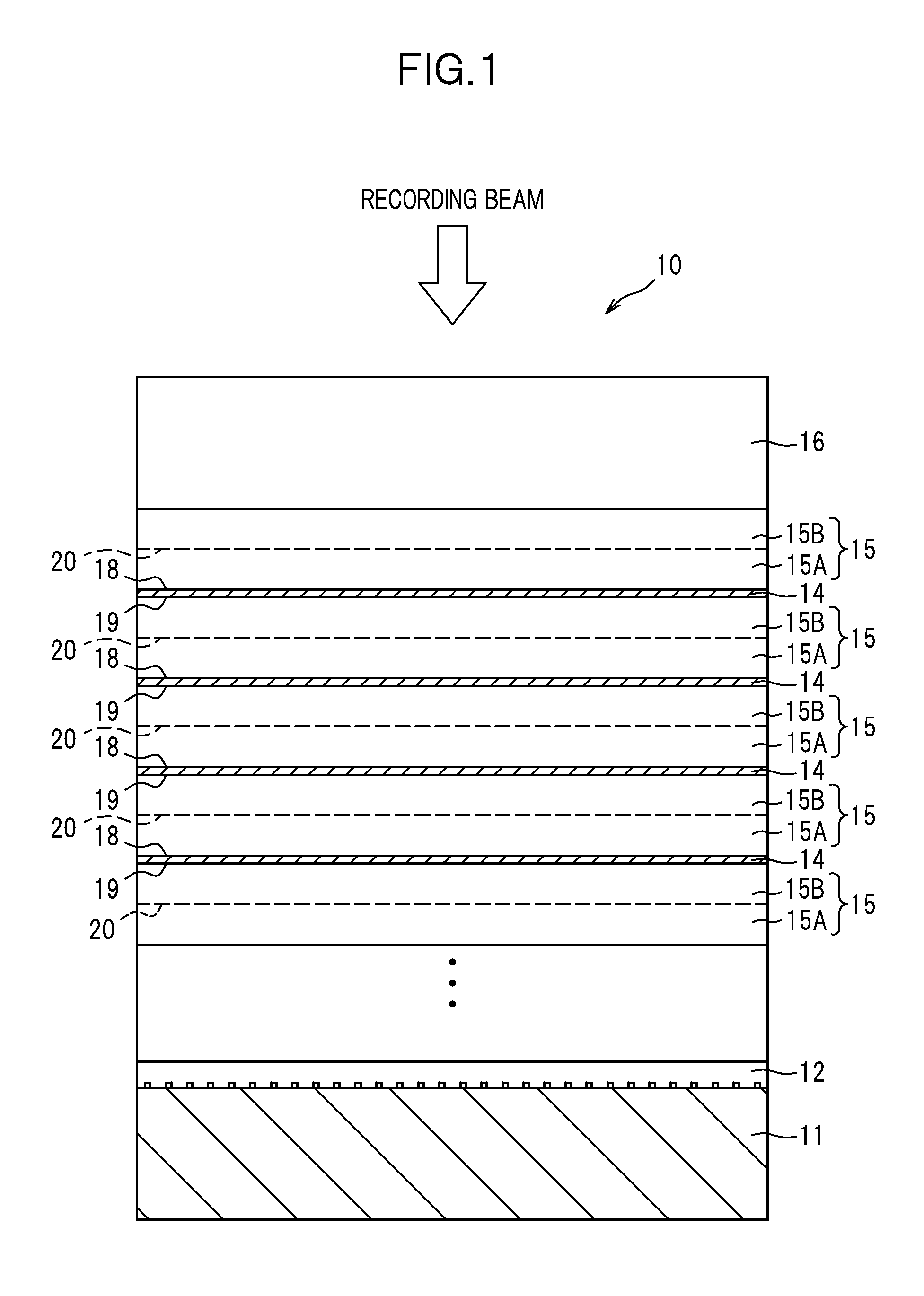
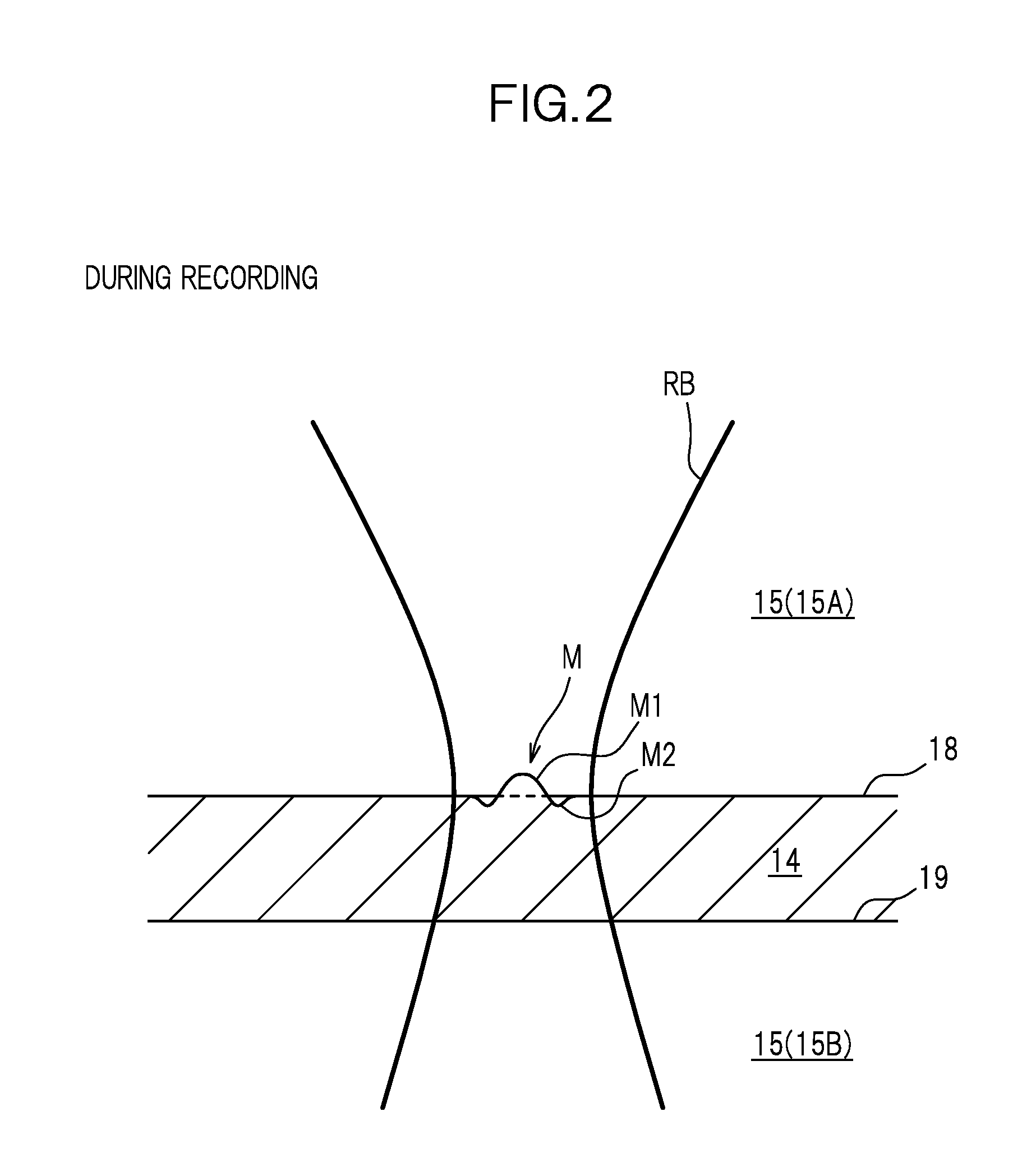
[0017]If the protrusion is formed at only one of the first interface and the second interface, the interface in which the protrusion is formed is used for reading out information; in this case, it is preferable that the difference between refractive indices of the materials is large at both sides of this interface so that the interface reflectivity becomes larger and thus reading the information can be performed easily. Meanwhile, the interface in which the protrusion is not formed is not used for reading out the information; in this case, it is preferable that the difference of refractive indices of the materials can be small at both sides of this interface so that the transmittance for a light beam used for recording or reading information (hereinafter referred to as a “record / readout beam”) (i.e., transmittance for both the first interface and the second interface) can be enhanced. Accordingly, in the case of multi-layered recording layers, the light beam can reach far deeper recording layers from the record / readout beam radiation side. This is advantageous for increasing the storage capacity by increasing the number of recording layers.
[0018]In the aforementioned configuration, it is preferable that the refractive index of the intermediate layer at the interface in which the protrusion is not formed is substantially equal to the refractive index of the recording layer. If the refractive indices of these layers located at both sides of the interface are substantially the same, the light reflectivity of this interface is substantially zero. Accordingly, in the case of multi-layered recording layers, the light beam can reach far deeper recording layers from the record / readout beam radiation side. This is advantageous for increasing the storage capacity by increasing the number of recording layers.

Problems solved by technology

However, according to the recording materials used for the conventional optical information recording medium, if the light absorption ratio is lowered, the recording layer will not receive sufficient energy from the recording beam, which results in insufficient recording sensitivity.

Method used


Image

  • Optical information recording medium
  • Optical information recording medium
  • Optical information recording medium

Examples


examples

[0077]Description will be given of experiments for recording on and erasing from an optical information recording medium according to the present invention.

1. Recording Material

[0078]In these examples, a recording material which contains a polymer binder and dye dispersed in the polymer binder was used.

[0079](1) Polymer Binder

[0080]Polyvinyl acetate (from Across Co., Ltd.; Mw: 101600) or polymethylmethacrylate (from SIGMA-ALDRICH Corporation) was used as the polymer binder.

[0081](2) Dye

[0082]Either one of or both of phthalocyanine-based one-photon absorption dye with the following structure C-1 and two-photon absorption dye with the following structure C-2 were used as the dye.

2. Formation Method for Recording Layer

[0083]Dye and a polymer binder were dissolved in a solvent (described later) while stirring to obtain a coating liquid. The coating liquid was applied to a glass substrate by spin coating to form a film on the glass substrate. The thickness of the film was 1 μm. The refra...

example 1

[0110]

Solventmethyl ethyl ketone (MEK) 7 gDyeC-1 compound 15 mgPolymer binderpolyvinyl acetate (PVAc)500 mg

example 2

[0111]Conditions of Example 2 were the same as those of Example 1, except that the following compound was used as the dye.

DyeC-2 compound72 mg


PUM

PropertyMeasurementUnit
thicknessaaaaaaaaaa
thicknessaaaaaaaaaa
thicknessaaaaaaaaaa

Abstract

An optical information recording medium 10 comprises a plurality of recording layers 14 and intermediate layers 15 each provided between the recording layers 14. Each of the recording layers 14 includes a polymer binder and dye dispersed in the polymer binder, and a thickness of each recording layer is equal to or greater than 50 nm. A first interface (near-side interface 18) is formed between a recording layer 14 and an intermediate layer 15 that is adjacent to the recording layer 14 on one side of the recording layer 14 in a thickness direction of the recording layer 14, and a second interface (far-side interface 19) is formed between the recording layer 14 and an intermediate layer 15 that is adjacent to the recording layer 14 on the other side of the recording layer 14 in the thickness direction of the recording layer 14. When the dye is irradiated with a recording beam and generates heat by absorption of the recording beam, the polymer binder undergoes a change in shape by the generated heat, so that at least one of the first interface and the second interface undergoes a change in shape and sticks out toward the intermediate layer 15 to form a protrusion, whereby information is recorded in the optical information recording medium 10.

Description

CROSS-REFERENCE TO RELATED APPLICATION(S)[0001]This application is a continuation application of International Application No. PCT / JP2011 / 072393 filed on Sep. 29, 2011, which claims priority to Japanese Patent Application No. 2010-234590 filed on Oct. 19, 2010, the disclosures of which are incorporated herein by reference in their entity.TECHNICAL FIELD[0002]The present invention relates to an optical information recording medium.BACKGROUND ART[0003]In general, as recording materials for an optical information recording medium, organic recording materials mainly consisting of dye and inorganic recording materials mainly consisting of metal have been used. These recording materials change (decomposition, phase change or the like) by making use of energy obtained from absorption of a recording beam, to thereby form recording spots. For applying this principle of recording spot formation, it is necessary that irradiation with the recording beam provides a recording material with energy...

Claims


Application Information

Patent Timeline
Patent Type & Authority Applications(United States)
IPC IPC(8): G11B7/244G11B7/24G11B7/24035G11B7/24038G11B7/246
CPCB82Y10/00G11B7/00452G11B7/24038G11B7/244G11B7/246G11B7/248G11B7/2531G11B7/245
Inventor MOCHIZUKI, HIDEHIROMIKAMI, TATSUO
Owner FUJIFILM CORP
Why Eureka
Try Eureka