Hydrocarbon fluid pipeline including RF heating station and related methods

a technology heating station, applied in the field of hydrocarbon fluid pipeline heating, can solve the problems of increasing the percentage of the overall fuel cost, hydrocarbon fluid pipeline, and increasing operational problems, and achieve the effect of reducing operational problems

Active Publication Date: 2013-09-12
HARRIS CORP
View PDF4 Cites 7 Cited by
  • Summary
  • Abstract
  • Description
  • Claims
  • Application Information

AI Technical Summary

Benefits of technology

[0015]This and other objects, features, and advantages in accordance with the present invention are provided by a hydrocarbon fluid pipeline that includes a plurality of pipeline segments connected together in end-to-end relation between first and second spaced apart geographic locations and configured to carry hydrocarbon fluid therethrough. The hydrocarbon fluid pipeline also includes a radio frequency (RF) heating station that includes an RF source, and an

Problems solved by technology

Transportation costs associated with a hydrocarbon fluid, for example, gasoline or other hydrocarbon resources, may account for an increased percentage of the overall fuel cost.
A hydrocarbon fluid pipeline in a particularly cold environment, such as, for example, Alaska, may be subject to increased operational issues that may result from heat loss.
Additionally, as flow rates in a hydrocarbon fluid pipeline decrease, temperature and turbulence decreases.
Some operational issues associated with reduced flow rates or reduced temperatures may include wax precipitation and deposition that forms at temperatures below 75° F., and water drop out, which may lead to increased corrosion and increased ice formation.
Other operational issues may include geotechnical issues, for example, formation of ice in buried sections o

Method used


Image

  • Hydrocarbon fluid pipeline including RF heating station and related methods
  • Hydrocarbon fluid pipeline including RF heating station and related methods
  • Hydrocarbon fluid pipeline including RF heating station and related methods

Examples


Embodiment Construction

[0023]The present invention will now be described more fully hereinafter with reference to the accompanying drawings, in which preferred embodiments of the invention are shown. This invention may, however, be embodied in many different forms and should not be construed as limited to the embodiments set forth herein. Rather, these embodiments are provided so that this disclosure will be thorough and complete, and will fully convey the scope of the invention to those skilled in the art. Like numbers refer to like elements throughout.

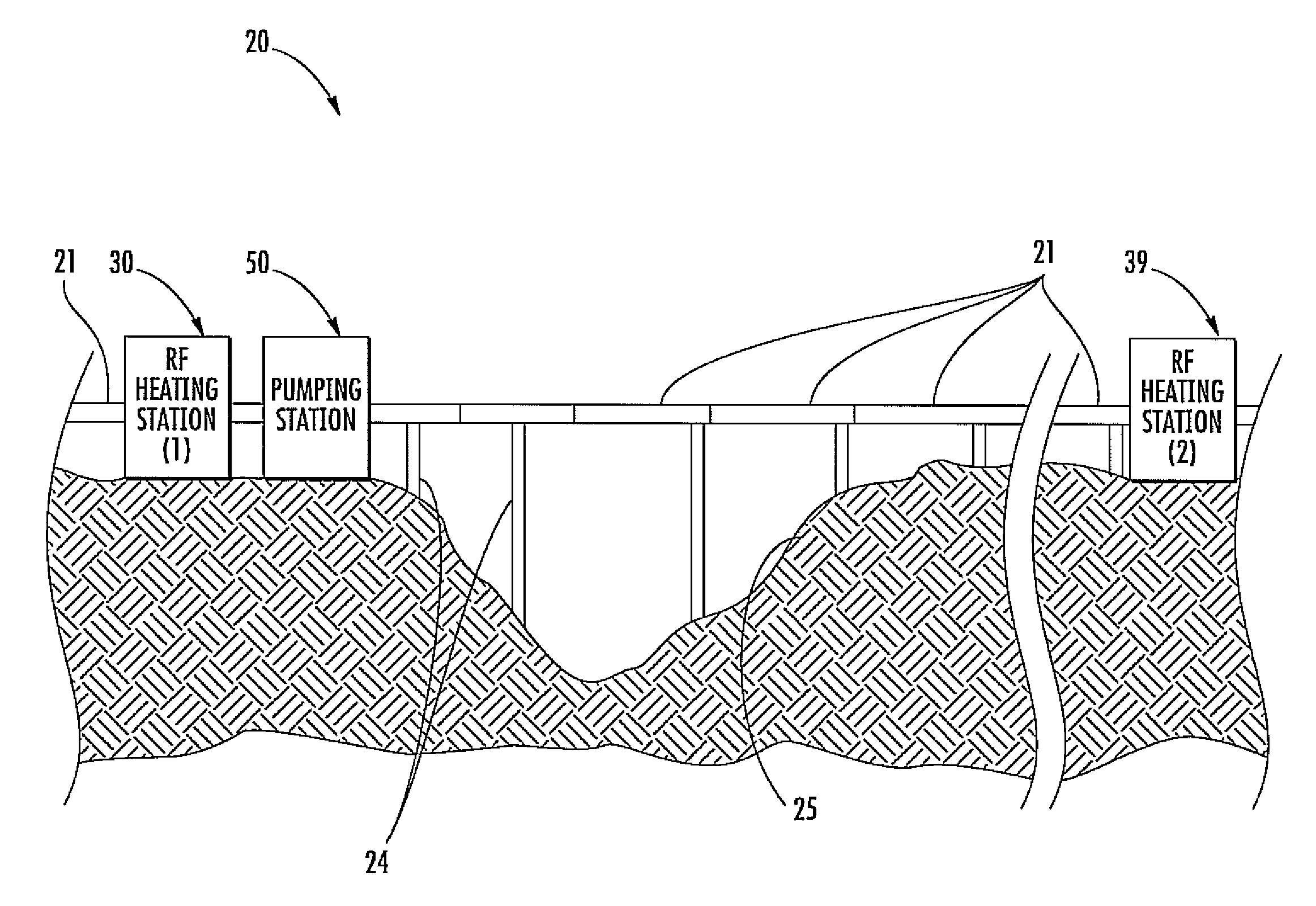
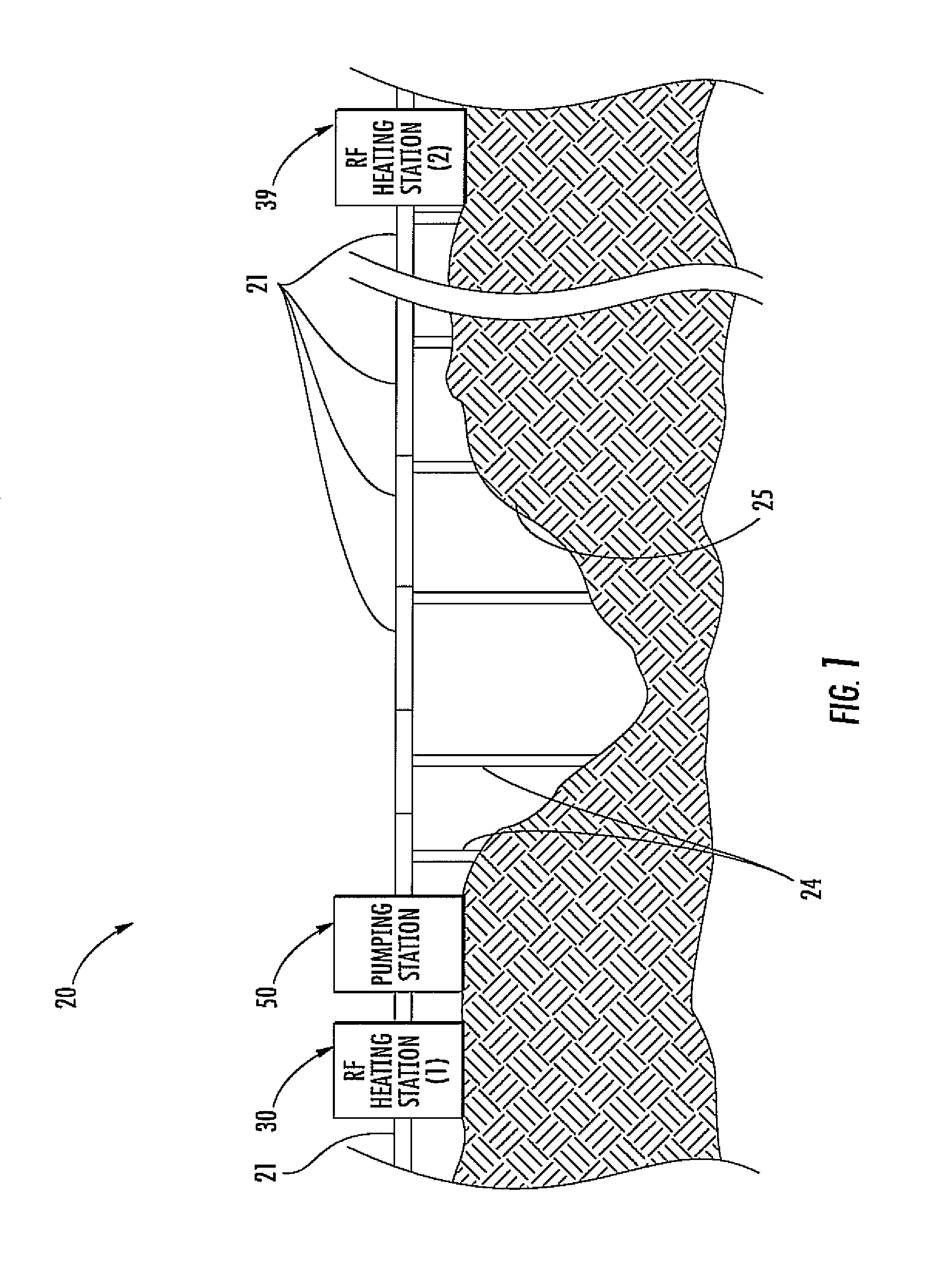
[0024]Referring initially to FIG. 1, a hydrocarbon fluid pipeline 20 includes pipeline segments 21 coupled together in end-to-end relation between first and second spaced apart geographic locations. The pipeline segments 21 may include metal, for example, so that they are electrically conductive. The hydrocarbon fluid pipeline 20 may carry crude oil, gasoline, or other hydrocarbon fluid therethrough, for example. More particularly, the hydrocarbon fluid pi...


PUM


Abstract

A hydrocarbon fluid pipeline may include pipeline segments connected together in end-to-end relation between first and second spaced apart geographic locations and configured to carry hydrocarbon fluid therethrough. The hydrocarbon fluid pipeline may also include a radio frequency (RF) heating station that may include an RF source and an RF heater between adjacent pipeline segments of the plurality thereof. The RF heater may include an inner tubular dielectric coupler between the adjacent pipeline segments, and an electrically conductive outer housing surrounding the inner tubular dielectric coupler and connected to the RF source to heat the hydrocarbon fluid.

Description

FIELD OF THE INVENTION[0001]The present invention relates to the field of hydrocarbon fluid pipelines, and, more particularly, to hydrocarbon fluid pipeline heating and related methods.BACKGROUND OF THE INVENTION[0002]Transportation costs associated with a hydrocarbon fluid, for example, gasoline or other hydrocarbon resources, may account for an increased percentage of the overall fuel cost. To reduce transportation costs associated with a hydrocarbon fluid, several methods for distributing the hydrocarbon fluid in bulk have been used. For example, container or tanker ships or vehicles may be used to transport a relatively large amount of hydrocarbon fluids. Another method for transporting a hydrocarbon fluid may be a hydrocarbon fluid pipeline, for example.[0003]One particular hydrocarbon transport pipeline is the Trans Alaska Pipeline System (TAPS). The Trans Alaska Pipeline System includes about 800 miles (1,287 km) of hydrocarbon fluid pipeline with a diameter of 48 inches (122...

Claims


Application Information

Patent Timeline
IPC IPC(8): F16L3/00H05B6/10F16L55/00F16L53/34
CPCF16L53/004H05B2214/03H05B6/802F16L53/34
Inventor BLUE, MARK ERNESTJACKSON, JR., RONALD EDWARDOTTOMANELLI, MICHAEL JOSEPHGEORGE, DONALD S.
Owner HARRIS CORP
Why Eureka
Try Eureka